Content .. 1130 1131 1132 1133 ..
Infiniti M35/M45 Y50. Manual - part 1132
TROUBLE DIAGNOSIS FOR SYMPTOMS
TF-35
C
E
F
G
H
I
J
K
L
M
A
B
TF
4.
CHECK AWD CONTROL UNIT
Check AWD control unit input/output signal. Refer to
TF-20, "AWD Control Unit Input/Output Signal Reference
OK or NG
OK
>> GO TO 5.
NG
>> Check AWD control unit pin terminals for damage or loose connection with harness connector. If
any items are damaged, repair or replace damaged parts.
5.
CHECK OUTPUT SIGNAL WITH UNIFIED METER AND A/C AMP.
With CONSULT-II
1.
Turn ignition switch “ON”. (Do not start engine.)
2.
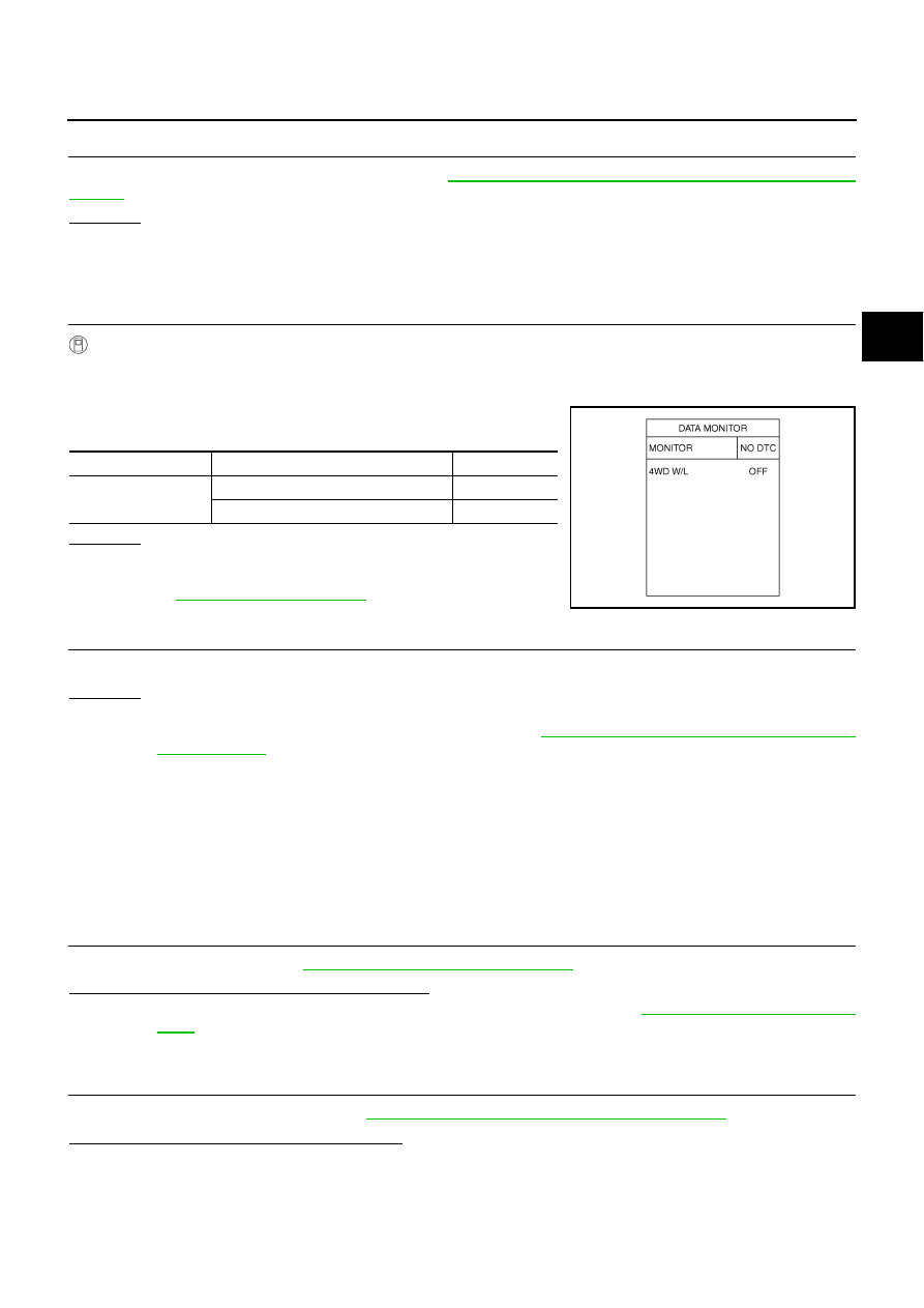
Select “DATA MONITOR” mode for “METER A/C AMP” with CONSULT-II.
3.
Start the engine, and then make sure that “4WD W/L” display
turns from "ON" to "OFF" after several seconds.
OK or NG
OK >> GO
TO
6.
NG
>> Perform trouble diagnosis for combination meter. Refer
to
.
6.
SYMPTOM CHECK
Check again.
OK or NG
OK
>> INSPECTION END
NG
>> Replace unified meter control unit assembly. Refer to
DI-27, "Disassembly and Assembly of Com-
Heavy Tight-Corner Braking Symptom Occurs When The Vehicle Is Driven and
The Steering Wheel Is Turned Fully to Either Side after The Engine Is Started
NDS000DW
NOTE:
Light tight-corner braking symptom may occur depending on driving conditions. This is not malfunc-
tion.
DIAGNOSTIC PROCEDURE
1.
CHECK SYSTEM FOR CAN COMMUNICATION LINE
Perform self-diagnosis. Refer to
TF-22, "SELF-DIAG RESULT MODE"
Is the “CAN COMM CIRCUIT [U1000]” displayed?
YES
>> Perform trouble diagnosis for CAN communication line. Refer to
NO
>> GO TO 2.
2.
CHECK ACCELERATOR PEDAL POSITION SIGNAL CIRCUIT
Perform self-diagnosis for ECM. Refer to
EC-55, "Emission-Related Diagnostic Information"
.
Is any malfunction detected by self-diagnosis?
YES
>> Check the malfunctioning system.
NO
>> GO TO 3.
Monitor item
Condition
Display value
4WD W/L
Ignition switch ON
ON
Start engine (after several seconds)
OFF
SDIA2065E