Infiniti M35/M45 Y50. Manual - part 10


  Index      Infiniti     Infiniti M35/M45 Y50 - service repair manual 2007 year


Search            copyright infringement  


Content   ..  8  9  10  11   ..


Infiniti M35/M45 Y50. Manual - part 10


TROUBLE DIAGNOSIS - GENERAL DESCRIPTION

ACS-33

[ICC]

C

D

E

F

G

H

I

J

L

M

A

B

ACS

ACTIVE TEST

CAUTION:

Never perform the active test while driving.

“ACTIVE TEST” cannot be started while ICC system warning lamp illuminates.
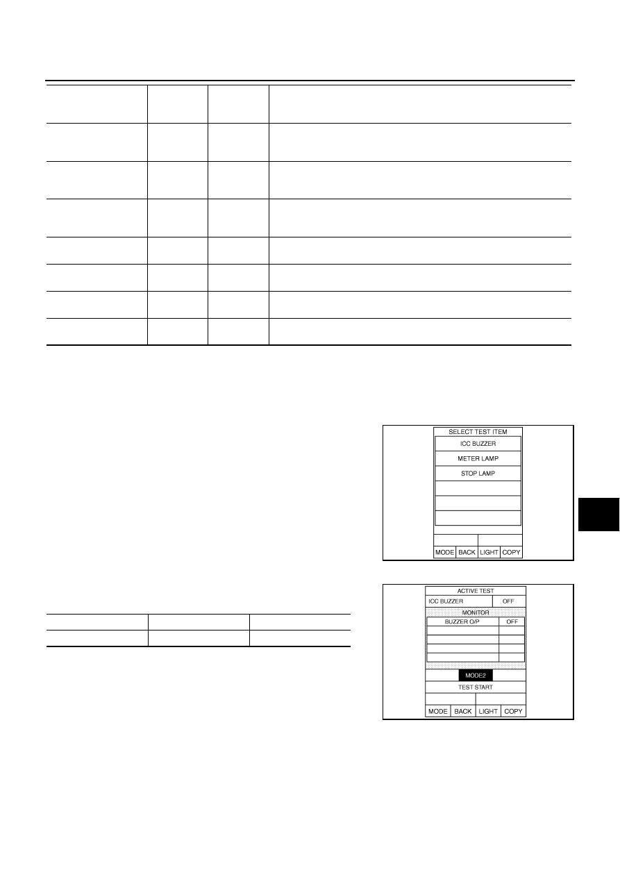
1.

Touch “ACTIVE TEST” on “SELECT DIAG MODE” screen. 

2.

Touch any of “ICC BUZZER”, “METER LAMP” and “STOP
LAMP” on selection screen.

3.

Touch necessary item and “START”.

4.

“ACTIVE TEST” screen will be shown.

ICC BUZZER 

Touch “TEST START” and “RESET” in “MODE2” to check if ICC
warning chime operates as in the following chart.

NP RANGE SW
[ON/OFF]

×

Indicates A/T position indicator lamp signal read from ICC sensor integrated 
unit through CAN communication (TCM transmits A/T position indicator 
lamp signal through CAN communication).

VHCL SPD AT
[km/h] or [mph]

×

Indicates vehicle speed calculated from A/T vehicle speed sensor read from 
ICC sensor integrated unit through CAN communication (TCM transmits A/
T vehicle speed sensor signal through CAN communication).

GEAR
[1, 2, 3, 4, 5]

×

Indicates A/T gear position read from ICC sensor integrated unit through 
CAN communication (TCM transmits current gear position signal through 
CAN communication).

MODE SIG
[OFF, ICC, ASCD]

×

Indicates the active mode from ICC or ASCD (conventional (fixed speed) 
cruise control mode). 

SET DISP IND
[ON/OFF]

×

Indicates [ON/OFF] status of SET switch indicator output.

DISTANCE
[m]

×

Indicates the distance from the vehicle ahead.

RELATIVE SPD
[m/s]

×

Indicates the relative speed of the vehicle ahead. 

Monitored Item [unit]

MAIN 

SIGNALS

SELEC-

TION FROM 

MENU

Description

PKIB8366E

BUZZER O/P

ON

OFF

Buzzer sound

Beep

Not activated

PKIB8368E

ACS-34

[ICC]

TROUBLE DIAGNOSIS - GENERAL DESCRIPTION

METER LAMP

Start engine.

Touch “ON” and “OFF” to check if MAIN switch indicator lamp
and ICC system warning lamp illuminate as in the following
chart.

STOP LAMP

Touch “ON” and “OFF” to check if stop lamp operates as in the fol-
lowing chart.

Self-Diagnostic Function

NKS004CY

WITH CONSULT-II

1.

Go to operation check after asking the customer for symptom information. Refer to 

ACS-12, "ACTION

TEST"

 .

2.

Stop vehicle, turn ignition switch OFF, then connect CONSULT-II and CONSULT-II CONVERTER to data
link connector.

3.

With engine started, touch “START (NISSAN BASED VHCL)”, “ICC”, “SELF-DIAG RESULTS” on CON-
SULT-II screen in this order.

CAUTION:

If “ICC” cannot be shown after several attempts, the ICC sensor integrated unit may have had mal-
function. Repair or replace it. Refer to 

GI-39, "CONSULT-II Data Link Connector (DLC) Circuit"

 .

4.

“DTC RESULTS” and “TIME” are indicated on “SELF-DIAG RESULTS”. “TIME” is used as a reference
data of diagnosis. It shows when malfunction is detected.

NOTE:
“TIME” shows the following.

0: malfunction is detected at present (from malfunction detection to ignition switch OFF).

CAN communication ([U1000], [U1010])

1 ~ 39: Displays when it is normal at present and finds malfunction in the past. It increases like
0

1

2...38

39 after returning to the normal condition whenever IGN OFF

ON. If it is over 39, it is

fixed to 39 until the self-diagnostic results are erased. It returns to 0 when malfunction is detected again
in the process.

Other than CAN communication (other than [U1000], [U1010]) 

1 ~ 49: Displays when it is normal at present and finds malfunction in the past. It increases like
0

1

2...48

49 after returning to the normal condition whenever IGN OFF

ON. If it is over 49, it is

fixed to 49 until the self-diagnostic results are erased. It returns to 0 when malfunction is detected again
in the process.

If “NO DTC...” is shown, check ICC system warning lamp. If any malfunction is indicated, GO TO step 5.

5.

According to 

ACS-40, "Diagnostic Trouble Code (DTC) Chart"

 , perform appropriate check, and repair or

replace malfunctioning part as necessary.

6.

Turn ignition switch OFF.

METER LAMP

ON

OFF

ICC system warning lamp

MAIN switch indicator 
lamp

Illuminated

OFF

PKIB8370E

STP LMP DRIVE

ON

OFF

Stop lamp

Turn ON

OFF

PKIB8369E

TROUBLE DIAGNOSIS - GENERAL DESCRIPTION

ACS-35

[ICC]

C

D

E

F

G

H

I

J

L

M

A

B

ACS

7.

Start engine and touch “START (NISSAN BASED VHCL)”, “ICC”, “SELF-DIAG RESULTS” and “ERASE”
on CONSULT-II display in turn to erase the memory.

CAUTION:

If the memory does not erase, go to 5.

8.

Perform ICC system running test (drive vehicle with ICC system ON), and make sure that ICC system
warning lamp does not illuminate.

WITHOUT CONSULT-II

1.

Go to operation check after asking the customer for symptom information. Refer to 

ACS-12, "ACTION

TEST"

 .

2.

Stop the vehicle and turn ignition switch OFF.

3.

Start engine.

4.

From 5 seconds through 15 seconds after start engine, press
RESUME/ACCELERATE switch 5 times, and SET/COAST
switch 5 times.

CAUTION:

Never turn the MAIN switch ON.

When operation above is not completed from 5 seconds
through 15 seconds, start again from above go to 3.

If self-diagnosis mode cannot be started after several
attempts, the ICC sensor integrated unit may have had
malfunction. Repair or replace it. Refer to 

ACS-36, "SELF-

DIAGNOSIS BY DOT MATRIX LCD WILL NOT RUN"

 .

5.

When self-diagnosis mode is started, DTC are shown on set vehicle speed indicator.

CAUTION:

DTC will disappear after 5 minutes.

When more than one malfunction is detected, a maximum of 3 code numbers can be stored; the
latest malfunction will be displayed first.

6.

Check 

ACS-40, "Diagnostic Trouble Code (DTC) Chart"

 , and repair or replace if necessary.

7.

After repair, erase DTC stored in the ICC sensor integrated unit.

8.

DTC 55 will be shown.

9.

Turn ignition switch OFF to exit the diagnosis.

10. Perform ICC system running test (drive vehicle with ICC system ON), and make sure that ICC system

warning lamp (Orange) does not illuminate.

PKIB8371E

PKIB8372E

ACS-36

[ICC]

TROUBLE DIAGNOSIS - GENERAL DESCRIPTION

Self-Diagnostic Erasing Method

1.

Stop the vehicle and turn ignition switch OFF.

2.

Start engine and start self-diagnosis.

3.

During self-diagnosis mode, press CANCEL switch 5 times, and
DISTANCE switch 5 times in this order.

CAUTION:

Press them within 10 seconds after pressing CANCEL
switch at first.

When operation is not completed within 10 seconds, start
again from step 2 above.

4.

DTC 55 will be shown.

CAUTION:

DTC of an existing malfunction will not be erased.

5.

Turn ignition switch OFF to exit the diagnosis.

6.

Perform ICC system running test (drive vehicle with ICC system ON), and make sure that ICC system
warning lamp (Orange) does not illuminate.

SELF-DIAGNOSIS BY DOT MATRIX LCD WILL NOT RUN

Possible Irregular Condition

PKIB8373E

PKIB8374E

Open or short lines

Symptoms

Malfunction causes

ICC sensor integrated unit power supply 
malfunction

No voltage supply from ignition switch

Fuse blown.

Harness open.

Harness shorted.

Ground cable not connected

Harness open.

Harness shorted.

ICC steering switch malfunction

No signal transmitted

Harness open.

Harness shorted.

Spiral cable open.

Spiral cable shorted.

ICC steering switch or ECM malfunction.

CAN communication system malfunction

Signal not transmitted

Harness open.

Harness shorted.

CAN communication malfunction.

Combination meter system malfunction

Indication not possible

Combination meter malfunction.

Unified meter and A/C amp. malfunction.

Dot matrix LCD malfunction.

ICC sensor integrated unit malfunction

ICC sensor integrated unit internal mal-
function.


Content   ..  8  9  10  11   ..