Infiniti I35 (A33). Manual - part 592
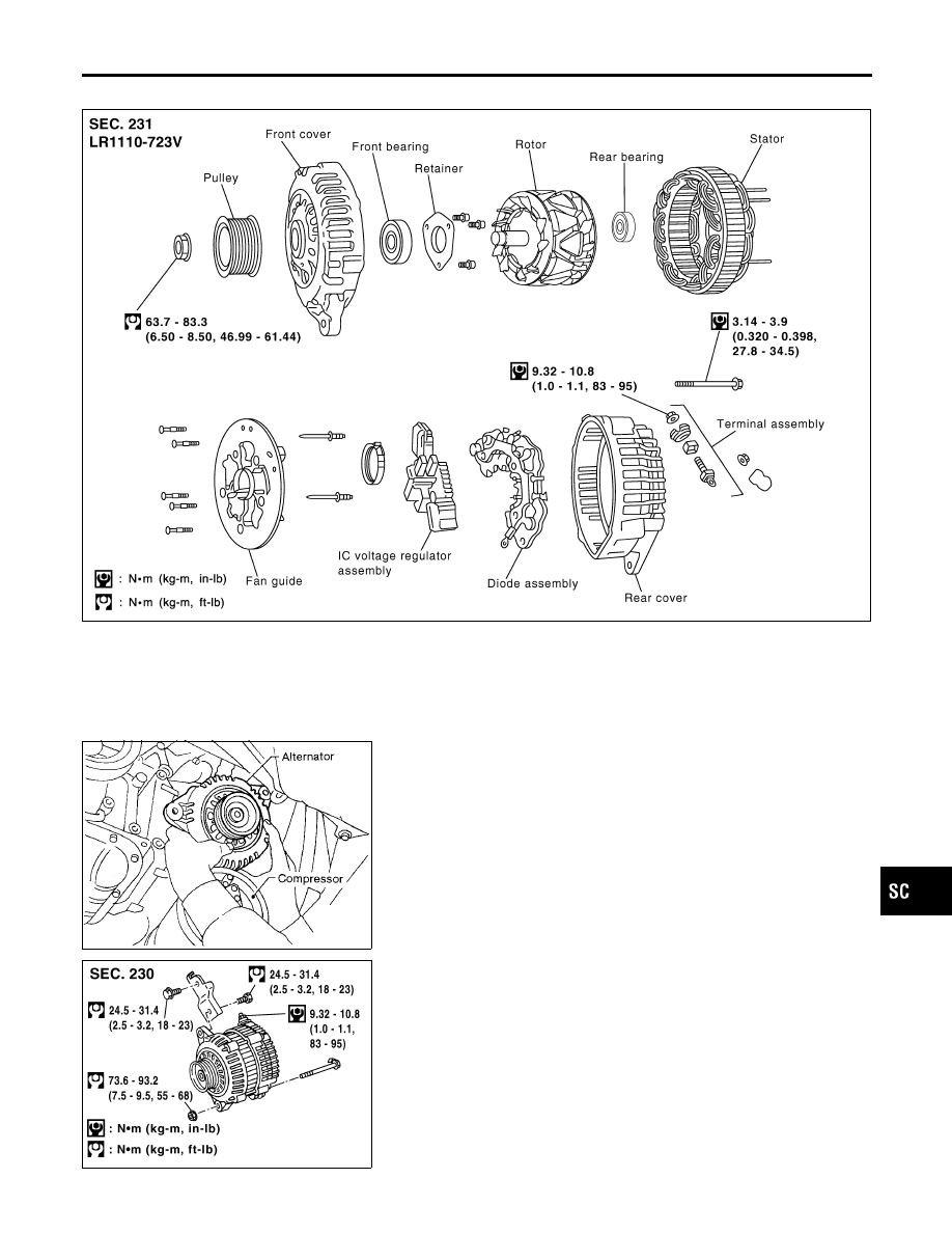
Construction
NHSC0012
SEL974Y
SEL460T
Removal and Installation
NHSC0013
REMOVAL
NHSC0013S01
1.
Remove engine undercover RH.
2.
Remove side inspection cover RH.
3.
Loosen belt idler pulley.
4.
Remove drive belt.
5.
Remove A/C compressor mounting bolts (four).
6.
Slide A/C compressor forward.
7.
Disconnect alternator harness connector.
8.
Remove alternator upper bolt and lower bolt.
SEL935Y
INSTALLATION
NHSC0013S02
To install, reverse the removal procedure.
GI
MA
EM
LC
EC
FE
AT
AX
SU
BR
ST
RS
BT
HA
EL
IDX
CHARGING SYSTEM
Construction
SC-29