Infiniti I35 (A33). Manual - part 503
SFE750A
SFE562A
Fuel Tank
NHFE0006
REMOVAL
NHFE0006S01
1.
Release fuel pressure from fuel line.
Refer to EC-55, “Fuel Pressure Release”.
2.
Disconnect battery ground cable.
3.
Drain fuel from fuel tank.
4.
Remove rear seat bottom. Refer to BT-53, “Removal and Instal-
lation”.
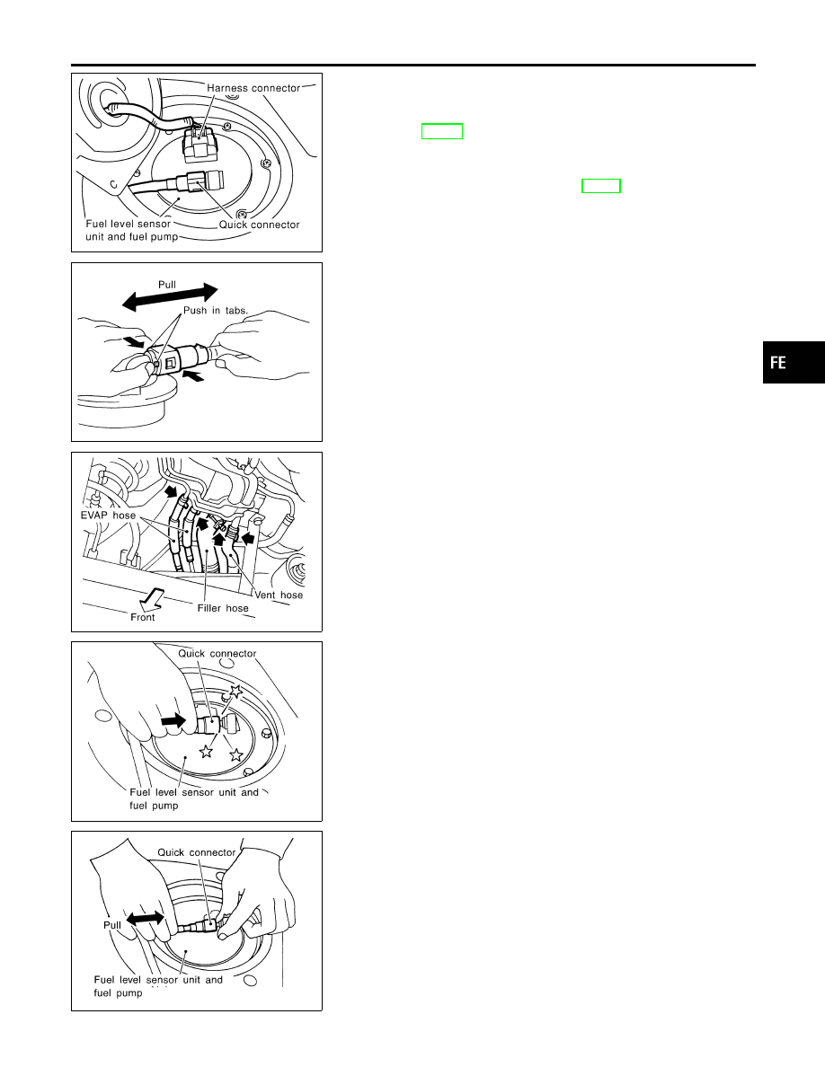
5.
Disconnect electrical connector.
6.
Disconnect the quick connector as follows.
a.
Put mating marks on tubes and connectors for correct instal-
lation.
b.
Hold the sides of the connector, push in tabs, and pull out the
tube inserted in the retainer.
CAUTION:
I
The quick connector can be disconnected when the push
in tabs are completely depressed. Do not twist it more
than necessary.
I
Do not use any tools to disconnect the quick connector.
I
Keep clean the connecting portion of the tube and the
quick connector.
SFE559AA
7.
Disconnect filler hose, vent hose and EVAP hose at fuel tank
side.
8.
Remove exhaust heat insulators.
9.
Remove fuel tank mounting band bolts while supporting fuel
tank.
10. Remove fuel tank.
SFE751A
INSTALLATION
NHFE0006S02
To install, reverse the removal procedure. Connect the quick con-
nector as follows:
I
Align mating marks on tubes and connectors for correct instal-
lation.
I
Be sure that the connecting portion of the tube and the quick
connectors is clean and smooth.
I
Align push in tabs with retainer openings.
I
Insert tube into the center of the connector until you hear a
click.
SFE752A
After connecting quick connector, make sure the connection is
firmly made using the following method.
I
Pull on the fuel tube and connector to make sure they are firmly
connected.
Make sure that there are no leakage at fuel line connections as
follows.
I
Apply fuel pressure to fuel lines with ignition switch turned ON
(with engine stopped). Then check that there are no leaks.
I
Start the engine, increase engine speed and verify that there
are no leaks again.
GI
MA
EM
LC
EC
AT
AX
SU
BR
ST
RS
BT
HA
SC
EL
IDX
FUEL SYSTEM
Fuel Tank
FE-5