Infiniti I35 (A33). Manual - part 398
SEL265
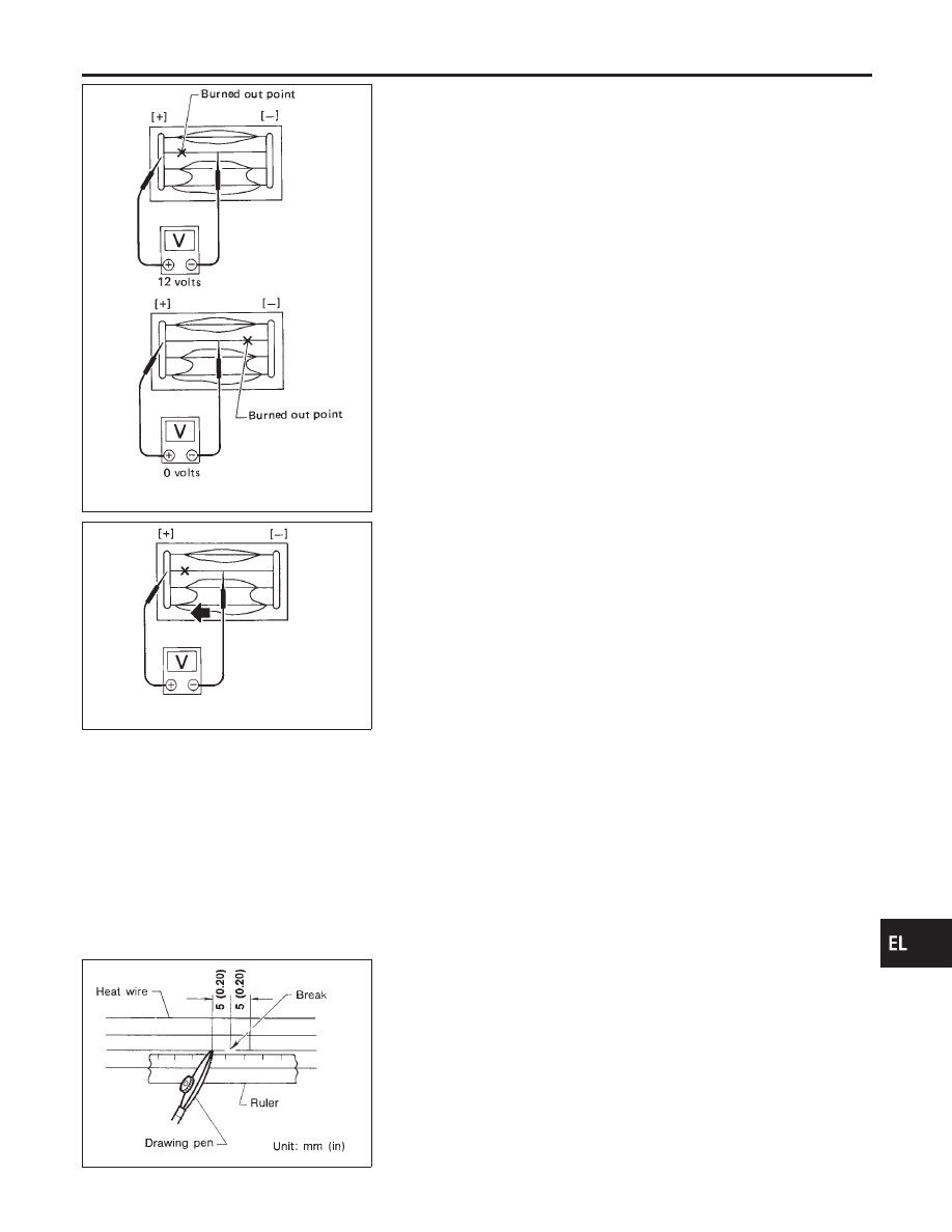
2.
If a filament is burned out, circuit tester registers 0 or 12 volts.
SEL266
3.
To locate burned out point, move probe to left and right along
filament. Test needle will swing abruptly when probe passes
the point.
Filament Repair
NHEL0078
REPAIR EQUIPMENT
NHEL0078S01
1)
Conductive silver composition (Dupont No. 4817 or equivalent)
2)
Ruler 30 cm (11.8 in) long
3)
Drawing pen
4)
Heat gun
5)
Alcohol
6)
Cloth
BE540
REPAIRING PROCEDURE
NHEL0078S02
1.
Wipe broken heat wire and its surrounding area clean with a
cloth dampened in alcohol.
2.
Apply a small amount of conductive silver composition to tip of
drawing pen.
Shake silver composition container before use.
3.
Place ruler on glass along broken line. Deposit conductive sil-
ver composition on break with drawing pen. Slightly overlap
existing heat wire on both sides [preferably 5 mm (0.20 in)] of
the break.
GI
MA
EM
LC
EC
FE
AT
AX
SU
BR
ST
RS
BT
HA
SC
IDX
REAR WINDOW DEFOGGER
Filament Check (Cont’d)
EL-193