Infiniti I35 (A33). Manual - part 346
 

  Index      Infiniti     Infiniti I35 (A33) - service repair manual 2004 year


Search            


Content   ..  344  345  346  347   ..


Infiniti I35 (A33). Manual - part 346


Diagnostic Procedure

NHEC1238

1

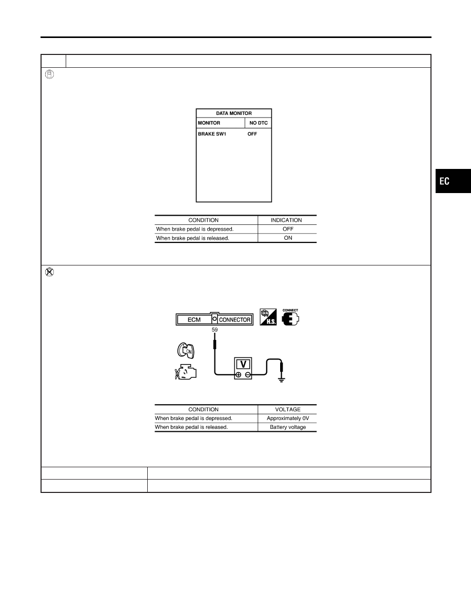
CHECK OVERALL FUNCTION-I

With CONSULT-II

1. Turn ignition switch ON.
2. Select “BRAKE SW1” in “DATA MONITOR” mode with CONSULT-II.
3. Check the indication of “BRAKE SW1” under the following conditions.

SEC011D

MTBL1557

Without CONSULT-II

1. Turn ignition switch ON.
2. Check voltage between ECM terminal 59 and ground under the following conditions.

SEC012D

MTBL1558

Refer to Wiring Diagram.

OK or NG

OK

©

GO TO 2.

NG

©

GO TO 3.

GI

MA

EM

LC

FE

AT

AX

SU

BR

ST

RS

BT

HA

SC

EL

IDX

ASCD BRAKE SWITCH

Diagnostic Procedure

EC-725

2

CHECK OVERALL FUNCTION-II

With CONSULT-II

See “BRAKE SW2” indication in “DATA MONITOR” mode.

SEC013D

MTBL1336

Without CONSULT-II

Check voltage between ECM terminal 55 and ground under the following conditions.

SEC014D

MTBL1337

Refer to Wiring Diagram.

OK or NG

OK

©

GO TO 14.

NG

©

GO TO 9.

ASCD BRAKE SWITCH

Diagnostic Procedure (Cont’d)

EC-726

3

CHECK ASCD BRAKE SWITCH POWER SUPPLY CIRCUIT

1. Turn ignition switch OFF.
2. Disconnect ASCD brake switch harness connector.
3. Turn ignition switch ON.
4. Check voltage between ASCD brake switch terminal 1 and ground with CONSULT-II or tester.

PBIB0857E

Voltage: Battery voltage

OK or NG

OK

©

GO TO 5.

NG

©

GO TO 4.

4

DETECT MALFUNCTIONING PART

Check the following.

I

Fuse block (J/B) connector E83

I

10A fuse

I

Harness for open or short between ASCD brake switch and fuse

©

Repair open circuit or short to ground or short to power in harness or connectors.

5

CHECK ASCD BRAKE SWITCH INPUT CIRCUIT FOR OPEN AND SHORT

1. Turn ignition switch OFF.
2. Disconnect ECM harness connector.
3. Check harness continuity between ECM terminal 59 and ASCD brake switch terminal 2.

Refer to Wiring Diagram.

Continuity should exist.

4. Also check harness for open to ground and short to power.

OK or NG

OK

©

GO TO 7.

NG

©

GO TO 6.

6

DETECT MALFUNCTIONING PART

Check the following.

I

Harness connectors E81, M15

I

Harness connectors M223, F53

I

Harness for open and short between ECM and ASCD brake switch

©

Repair open circuit or short to ground or short to power in harness or connectors.

GI

MA

EM

LC

FE

AT

AX

SU

BR

ST

RS

BT

HA

SC

EL

IDX

ASCD BRAKE SWITCH

Diagnostic Procedure (Cont’d)

EC-727

7

CHECK ASCD BRAKE SWITCH

Refer to “Component Inspection”, EC-628.

OK or NG

OK

©

GO TO 8.

NG

©

Replace ASCD brake switch.

8

DETECT MALFUNCTIONING PART

Check the following.

I

Harness connectors E81, M15

I

Harness connectors M223, F53

©

Repair open circuit or short to ground or short to power in harness or connectors.

9

CHECK STOP LAMP SWITCH POWER SUPPLY CIRCUIT

1. Turn ignition switch OFF.
2. Disconnect stop lamp switch harness connector.
3. Check voltage between stop lamp switch terminal 1 and ground with CONSULT-II or tester.

PBIB0117E

Voltage: Battery voltage

OK or NG

OK

©

GO TO 11.

NG

©

GO TO 10.

10

DETECT MALFUNCTIONING PART

Check the following.

I

Fuse block (J/B) connector M17

I

15A fuse

I

Harness connectors M15, E81

I

Harness for open or short between stop lamp switch and fuse

©

Repair open circuit or short to ground in harness or connectors.

ASCD BRAKE SWITCH

Diagnostic Procedure (Cont’d)

EC-728


Content   ..  344  345  346  347   ..