Infiniti I35 (A33). Manual - part 317


  Index      Infiniti     Infiniti I35 (A33) - service repair manual 2004 year


Search            


Content   ..  315  316  317  318   ..


Infiniti I35 (A33). Manual - part 317


12

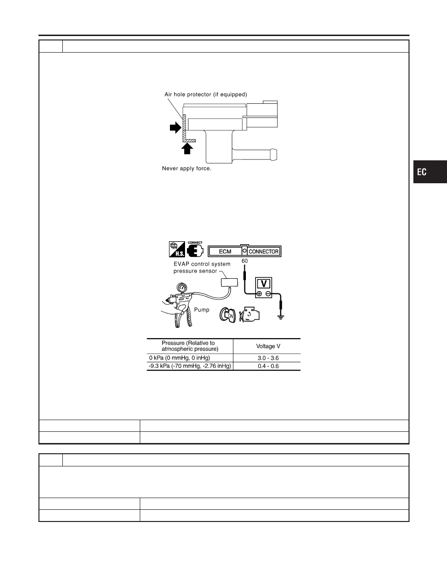
CHECK EVAP CONTROL SYSTEM PRESSURE SENSOR

1. Remove EVAP control system pressure sensor with its harness connector connected.

CAUTION:

Never apply force to the air hole protector of the sensor if equipped.

SEF799W

2. Remove hose from EVAP control system pressure sensor.
3. Turn ignition switch ON.
4. Use pump to apply vacuum and pressure to EVAP control system pressure sensor as shown in figure.

CAUTION:

I

Always calibrate the vacuum pump gauge when using it.

I

Do not apply below −20 kPa (−150 mmHg, −5.91 inHg) or over 20 kPa (150 mmHg, 5.91 inHg) of pressure.

5. Check input voltage between ECM terminal 84 and ground.

SEC908C

MTBL1159

CAUTION:

Discard and EVAP control system pressure sensor which has been dropped from a height of more than 0.5 m
(19.7 in) onto a hard surface such as a concrete floor; use a new one.

OK or NG

OK

©

GO TO 13.

NG

©

Replace EVAP control system pressure sensor.

13

CHECK RUBBER TUBE FOR CLOGGING

1. Disconnect rubber tube connected to EVAP canister vent control valve.
2. Check the rubber tube for clogging.

OK or NG

OK

©

GO TO 14.

NG

©

Clean the rubber tube using an air blower.

GI

MA

EM

LC

FE

AT

AX

SU

BR

ST

RS

BT

HA

SC

EL

IDX

DTC P1491 VACUUM CUT VALVE BYPASS VALVE

Diagnostic Procedure (Cont’d)

EC-609

14

CHECK EVAP CANISTER VENT CONTROL VALVE-I

1. Remove EVAP canister vent control valve from EVAP canister.
2. Check portion of EVAP canister vent control valve for being rusted.

SEF376Z

OK or NG

OK

©

GO TO 15.

NG

©

Replace EVAP canister vent control valve.

15

CHECK EVAP CANISTER VENT CONTROL VALVE-II

With CONSULT-II

1. Reconnect harness disconnected connectors.
2. Turn ignition switch ON.
3. Perform “VENT CONTROL/V” in “ACTIVE TEST” mode.
4. Check air passage continuity and operation delay time.

SEC158D

Without CONSULT-II

Check air passage continuity and operation delay time under the following conditions.

SEF378Z

Make sure new O-ring is installed properly.

OK or NG

OK

©

GO TO 17.

NG

©

GO TO 16.

DTC P1491 VACUUM CUT VALVE BYPASS VALVE

Diagnostic Procedure (Cont’d)

EC-610

16

CHECK EVAP CANISTER VENT CONTROL VALVE-III

1. Clean the air passage (Portion to B) of EVAP canister vent control valve using an air blower.
2. Perform the Test No. 15 again.

OK or NG

OK

©

GO TO 17.

NG

©

Replace EVAP canister vent control valve.

17

CHECK INTERMITTENT INCIDENT

Refer to “TROUBLE DIAGNOSIS FOR INTERMITTENT INCIDENT”, EC-152.

©

INSPECTION END

GI

MA

EM

LC

FE

AT

AX

SU

BR

ST

RS

BT

HA

SC

EL

IDX

DTC P1491 VACUUM CUT VALVE BYPASS VALVE

Diagnostic Procedure (Cont’d)

EC-611

SEC005D

Component Description

NHEC1208

ASCD steering switch has variant values of electrical resistance for
each button. ECM reads voltage variation of switch, and deter-
mines which button is operated.
Refer to EC-54 for the ASCD function.

CONSULT-II Reference Value in Data Monitor
Mode

NHEC1209

Specification data are reference values.

MONITOR ITEM

CONDITION

SPECIFICATION

MAIN SW

I

Ignition switch: ON

I

MAIN switch: Pressed

ON

I

MAIN switch: Released

OFF

CANCEL SW

I

Ignition switch: ON

I

CANCEL switch: Pressed

ON

I

CANCEL switch: Released

OFF

RESUME/ACC SW

I

Ignition switch: ON

I

RESUME/ACCEL switch:
Pressed

ON

I

RESUME/ACCEL switch:
Released

OFF

SET SW

I

Ignition switch: ON

I

SET/COAST switch:
Pressed

ON

I

SET/COAST switch:
Released

OFF

On Board Diagnosis Procedure

NHEC1462

This self-diagnosis has the one trip detection logic. The MIL will not light up for this self-diagnosis.
NOTE:
If DTC P1564 is displayed with DTC P0605, first perform the trouble diagnosis for DTC P0605. Refer to
EC-442.

DTC No.

Trouble diagnosis name

DTC Detecting Condition

Possible cause

P1564
1564

ASCD steering switch

I

An excessively high voltage signal
from the ASCD steering switch is
sent to ECM.

I

ECM detects that input signal from
the ASCD steering switch is out of
the specified range.

I

ECM detects that the ASCD steer-
ing switch is stuck ON.

I

Harness or connectors
(The ASCD steering switch circuit
is open or shorted.)

I

ASCD steering switch

I

ECM

DTC P1564 ASCD STEERING SWITCH

Component Description

EC-612


Content   ..  315  316  317  318   ..