Infiniti I30 (A33). Manual - part 312


  Index      Infiniti     Infiniti I30 (A33) - service repair manual 2001 year


Search            


Content   ..  310  311  312  313   ..


Infiniti I30 (A33). Manual - part 312


17

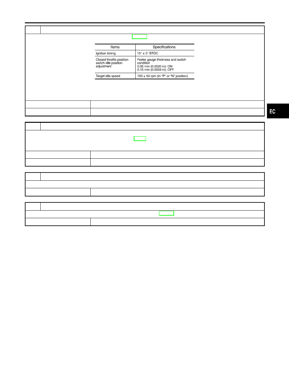
ADJUST THROTTLE POSITION SWITCH

Check the following items. Refer to “Basic Inspection”, EC-109.

MTBL0595

Is it possible to adjust closed throttle position switch?

Yes or No

Yes

©

GO TO 18.

No

©

Replace throttle position switch.

18

CHECK EVAP PURGE LINE

Inspect EVAP purge line (pipe and rubber tube). Check for evidence of leaks.
Refer to “EVAPORATIVE EMISSION LINE DRAWING”, EC-36.

OK or NG

OK

©

GO TO 19.

NG

©

Replace it.

19

CLEAN EVAP PURGE LINE

Clean EVAP purge line (pipe and rubber tube) using air blower.

©

GO TO 20.

20

CHECK INTERMITTENT INCIDENT

Refer to “TROUBLE DIAGNOSIS FOR INTERMITTENT INCIDENT”, EC-144.

©

INSPECTION END

GI

MA

EM

LC

FE

AT

AX

SU

BR

ST

RS

BT

HA

SC

EL

IDX

DTC P1447 EVAPORATIVE EMISSION (EVAP) CONTROL SYSTEM PURGE

FLOW MONITORING

Diagnostic Procedure (Cont’d)

EC-563

SEF032W

SEF267X

Component Description

NHEC0338

NOTE:
If DTC P1448 is displayed with P0440, perform trouble diagno-
sis for DTC P1448 first.
The EVAP canister vent control valve is located on the EVAP can-
ister and is used to seal the canister vent.
This solenoid valve responds to signals from the ECM. When the
ECM sends an ON signal, the coil in the solenoid valve is ener-
gized. A plunger will then move to seal the canister vent. The abil-
ity to seal the vent is necessary for the on board diagnosis of other
evaporative emission control system components.
This solenoid valve is used only for diagnosis, and usually remains
opened.
When the vent is closed, under normal purge conditions, the
evaporative emission control system is depressurized and allows
“EVAP Control System (Small Leak)” diagnosis.

CONSULT-II Reference Value in Data Monitor
Mode

NHEC0339

Specification data are reference values.

MONITOR ITEM

CONDITION

SPECIFICATION

VENT CONT/V

I

Ignition switch: ON

OFF

On Board Diagnosis Logic

NHEC0341

Malfunction is detected when EVAP canister vent control valve
remains opened under specified driving conditions.

Possible Cause

NHEC0591

I

EVAP canister vent control valve

I

EVAP control system pressure sensor and circuit

I

Blocked rubber tube to EVAP canister vent control valve

I

Water separator

I

EVAP canister is saturated with water.

I

Vacuum cut valve

DTC P1448 EVAPORATIVE EMISSION (EVAP) CANISTER VENT CONTROL

VALVE (OPEN)

Component Description

EC-564

DTC Confirmation Procedure

NHEC0342

NOTE:

I

If DTC P1448 is displayed with P0440 or P1440, perform
trouble diagnosis for DTC P1448 first.

I

If

“DTC

Confirmation

Procedure”

has

been

previously

conducted, always turn ignition switch “OFF” and wait at least
10 seconds before conducting the next test.

SEF565X

SEF566X

SEF567X

WITH CONSULT-II

NHEC0342S01

TESTING CONDITION:

I

Perform “DTC WORK SUPPORT” when the fuel level is
between 1/4 to 3/4 full and vehicle is placed on flat level
surface.

I

Always perform test at a temperature of 0 to 30°C (32 to
86°F).

1)

Turn ignition switch “ON”.

2)

Turn ignition switch “OFF” and wait at least 10 seconds.

3)

Turn ignition switch “ON” and select “DATA MONITOR” mode
with CONSULT-II.

4)

Make sure that the following conditions are met.

COOLAN TEMP/S

0 - 70°C (32 - 158°F)

INT/A TEMP SE

0 - 30°C (32 - 86°F)

5)

Select “EVAP SML LEAK P0440/P1440” of “EVAPORATIVE
SYSTEM” in “DTC WORK SUPPORT” mode with CONSULT-
II.
Follow the instruction displayed.
If the engine speed cannot be maintained within the range
displayed on the CONSULT-II screen, go to “Basic Inspection”,
EC-109.

6)

Make sure that “OK” is displayed.
If “NG” is displayed, go to the following step.

NOTE:
Make sure that EVAP hoses are connected to EVAP canister
purge volume control solenoid valve properly.
7)

Stop engine and wait at least 10 seconds, then turn “ON”.

8)

Disconnect hose from water separator.

9)

Select “VENT CONTROL/V” of “ACTIVE TEST” mode with
CONSULT-II.

10) Touch “ON” and “OFF” alternately.

SEF223Y

11) Make sure the following.

Condition

VENT CONTROL/V

Air passage continuity

between and B

ON

No

OFF

Yes

If the result is NG, go to “Diagnostic Procedure”, EC-568.
If the result is OK, go to “Diagnostic Procedure” for DTC
P0440, EC-364.

GI

MA

EM

LC

FE

AT

AX

SU

BR

ST

RS

BT

HA

SC

EL

IDX

DTC P1448 EVAPORATIVE EMISSION (EVAP) CANISTER VENT CONTROL

VALVE (OPEN)

DTC Confirmation Procedure

EC-565

AEC783A

Overall Function Check

NHEC0343

Use this procedure to check the overall function of the EVAP can-
ister vent control valve circuit. During this check, a DTC might not
be confirmed.

WITH GST

NHEC0343S01

1)

Disconnect hose from water separator.

2)

Disconnect EVAP canister vent control valve harness connec-
tor.

3)

Verify the following.

Condition

Air passage continuity

12V direct current supply between ter-
minals 1 and 2

No

No supply

Yes

If the result is NG, go to “Diagnostic Procedure”, EC-568.
If the result is OK, go to “Diagnostic Procedure” for DTC
P0440, EC-364.

DTC P1448 EVAPORATIVE EMISSION (EVAP) CANISTER VENT CONTROL

VALVE (OPEN)

Overall Function Check

EC-566


Content   ..  310  311  312  313   ..