Infiniti I30 (A33). Manual - part 297


  Index      Infiniti     Infiniti I30 (A33) - service repair manual 2001 year


Search            


Content   ..  295  296  297  298   ..


Infiniti I30 (A33). Manual - part 297


PROCEDURE B

NHEC0560S02

1

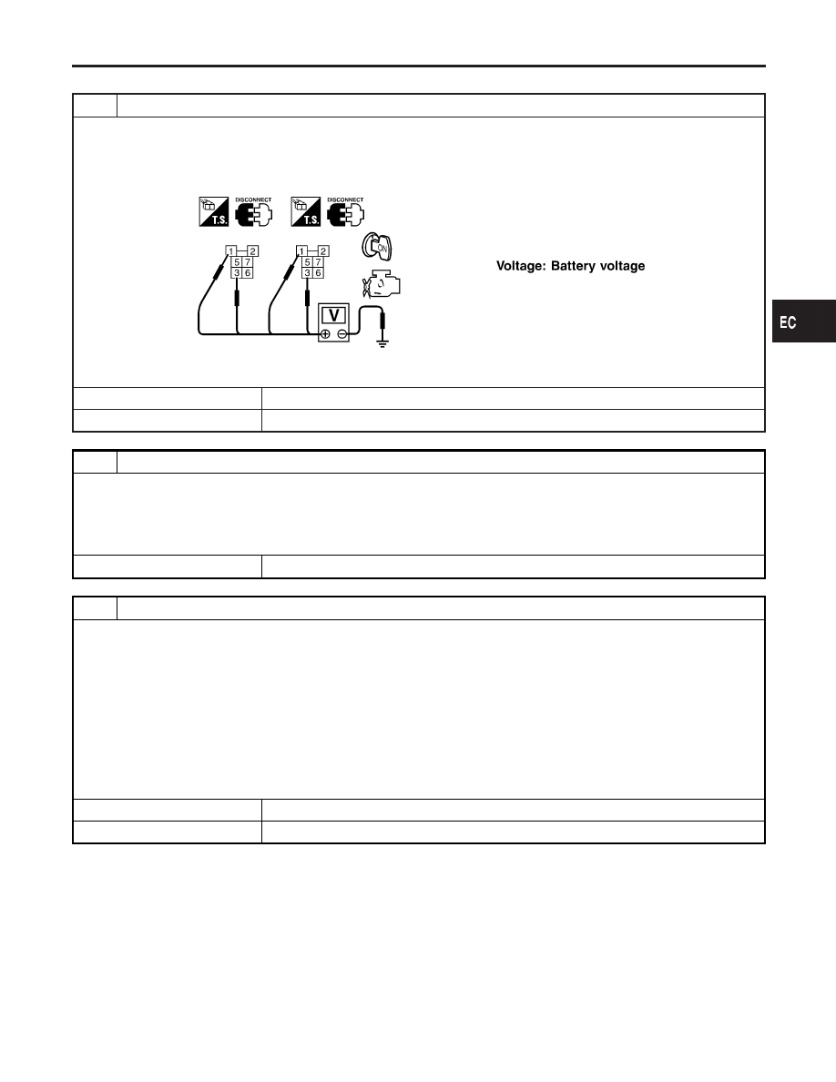
CHECK COOLING FAN POWER SUPPLY CIRCUIT

1. Turn ignition switch “OFF”.
2. Disconnect cooling fan relays-2 and -3.
3. Turn ignition switch “ON”.
4. Check voltage between cooling fan relays-2 and -3 terminals 1, 3 and ground with CONSULT-II or tester.

SEF593X

OK or NG

OK

©

GO TO 3.

NG

©

GO TO 2.

2

DETECT MALFUNCTIONING PART

Check the following.

I

Joint connector-8

I

Joint connector-9

I

Harness for open or short between cooling fan relays-2 and -3 and joint connectors-8, -9

I

Harness for open or short between cooling fan relays-2 and -3 and joint connectors-8, -9

©

Repair harness or connectors.

3

CHECK COOLING FAN GROUND CIRCUIT FOR OPEN AND SHORT

1. Turn ignition switch “OFF”.
2. Disconnect cooling fan motor-1 harness connector and cooling fan motor-2 harness connector.
3. Check harness continuity between cooling fan relay-2 terminal 5 and cooling fan motor-1 terminal 1, cooling fan relay-2

terminal 7 and cooling fan motor-1 terminal 4, cooling fan relay-2 terminal 6 and body ground. Refer to Wiring Diagram.

Continuity should exist.

4. Also check harness for short to ground and short to power.
5. Check harness continuity between cooling fan relay-3 terminal 5 and cooling fan motor-2 terminal 1, cooling fan relay-3

terminal 7 and cooling fan motor-2 terminal 4, cooling fan relay-3 terminal 6 and body ground. Refer to Wiring Diagram.

Continuity should exist.

6. Also check harness for short to ground and short to power.

OK or NG

OK

©

GO TO 4.

NG

©

Repair open circuit or short to ground or short to power in harness or connectors.

GI

MA

EM

LC

FE

AT

AX

SU

BR

ST

RS

BT

HA

SC

EL

IDX

DTC P1217 ENGINE OVER TEMPERATURE (OVERHEAT)

Diagnostic Procedure (Cont’d)

EC-503

4

CHECK COOLING FAN OUTPUT SIGNAL CIRCUIT FOR OPEN AND SHORT

1. Disconnect ECM harness connector.
2. Check harness continuity between ECM terminal 34 and cooling fan relay-2 terminal 2, cooling fan relay-3 terminal 2.

Refer to Wiring Diagram.

Continuity should exist.

3. Also check harness for short to ground and short to power.

OK or NG

OK

©

GO TO 6.

NG

©

GO TO 5.

5

DETECT MALFUNCTIONING PART

Check the following.

I

Harness connectors E8, E17

I

Joint connector-10

I

Harness for open or short between cooling fan relays-2 and -3 and ECM

©

Repair open circuit or short to ground or short to power in harness or connectors.

6

CHECK COOLING FAN RELAYS-2 AND -3

Check continuity between cooling fan relay-2, -3 terminals 3 and 5, 6 and 7 under the following conditions.

SEF591X

OK or NG

OK

©

GO TO 7.

NG

©

Replace cooling fan relays.

7

CHECK COOLING FAN MOTORS

Supply battery voltage between the following terminals and check operation.

SEF592X

OK or NG

OK

©

GO TO 8.

NG

©

Replace cooling fan motors.

DTC P1217 ENGINE OVER TEMPERATURE (OVERHEAT)

Diagnostic Procedure (Cont’d)

EC-504

8

CHECK INTERMITTENT INCIDENT

1. Perform “TROUBLE DIAGNOSIS FOR INTERMITTENT INCIDENT”, EC-144.

©

INSPECTION END

Main 12 Causes of Overheating

NHEC0561

Engine

Step

Inspection item

Equipment

Standard

Reference page

OFF

1

I

Blocked radiator

I

Blocked condenser

I

Blocked radiator grille

I

Blocked bumper

I

Visual

No blocking

2

I

Coolant mixture

I

Coolant tester

50 - 50% coolant mixture See MA-11, “RECOM-

MENDED FLUIDS AND
LUBRICANTS”.

3

I

Coolant level

I

Visual

Coolant up to MAX level
in reservoir tank and
radiator filler neck

See MA-14, “Changing
Engine Coolant”.

4

I

Radiator cap

I

Pressure tester

59 - 98 kPa
(0.6 - 1.0 kg/cm

2

, 9 - 14

psi) (Limit)

See LC-10, “System
Check”.

ON*

2

5

I

Coolant leaks

I

Visual

No leaks

See LC-10, “System
Check”.

ON*

2

6

I

Thermostat

I

Touch the upper and
lower radiator hoses

Both hoses should be
hot

See LC-15, “Thermostat”
and LC-17, “Radiator”.

ON*

1

7

I

Cooling fan

I

CONSULT-II

Operating

See trouble diagnosis for
DTC P1217 (EC-489).

OFF

8

I

Combustion gas leak

I

Color checker chemi-
cal tester 4 Gas ana-
lyzer

Negative

ON*

3

9

I

Coolant temperature
gauge

I

Visual

Gauge less than 3/4
when driving

I

Coolant overflow to
reservoir tank

I

Visual

No overflow during driv-
ing and idling

See MA-14, “Changing
Engine Coolant”.

OFF*

4

10

I

Coolant return from
reservoir tank to radia-
tor

I

Visual

Should be initial level in
reservoir tank

See MA-13, “ENGINE
MAINTENANCE”.

OFF

11

I

Cylinder head

I

Straight gauge feeler
gauge

0.1 mm (0.004 in) Maxi-
mum distortion (warping)

See EM-41, “Inspection”.

12

I

Cylinder block and pis-
tons

I

Visual

No scuffing on cylinder
walls or piston

See EM-61, “Inspection”.

*1: Turn the ignition switch ON.
*2: Engine running at 3,000 rpm for 10 minutes.
*3: Drive at 90 km/h (55 MPH) for 30 minutes and then let idle for 10 minutes.
*4: After 60 minutes of cool down time.
For more information, refer to LC-22, “OVERHEATING CAUSE ANALYSIS”.

GI

MA

EM

LC

FE

AT

AX

SU

BR

ST

RS

BT

HA

SC

EL

IDX

DTC P1217 ENGINE OVER TEMPERATURE (OVERHEAT)

Diagnostic Procedure (Cont’d)

EC-505

Component Description

NHEC0286

IGNITION COIL & POWER TRANSISTOR

NHEC0286S01

The ignition signal from the ECM is sent to and amplified by the power transistor. The power transistor turns
on and off the ignition coil primary circuit. This on-off operation induces the proper high voltage in the coil
secondary circuit.

SEF274X

On Board Diagnosis Logic

NHEC0288

Malfunction is detected when the ignition signal in the primary cir-
cuit is not sent to ECM during engine cranking or running.

Possible Cause

NHEC0572

I

Harness or connectors (The ignition primary circuit is open or
shorted.)

I

Power transistor unit built into ignition coil

I

Condenser

I

Crankshaft position sensor (REF)

I

Crankshaft position sensor (REF) circuit

SEF058Y

DTC Confirmation Procedure

NHEC0289

NOTE:

I

If

“DTC

Confirmation

Procedure”

has

been

previously

conducted, always turn ignition switch “OFF” and wait at least
10 seconds before conducting the next test.

I

If DTC P1320 is displayed with DTC P0335, P0340, P1335
or P1336, perform trouble diagnosis for DTC P0335,
P0340, P1335 or P1336 first. Refer to EC-343, 
EC-351,
EC-517 or EC-523.

DTC P1320 IGNITION SIGNAL

Component Description

EC-506


Content   ..  295  296  297  298   ..