Infiniti I30 (A33). Manual - part 238
Possible Cause
NHEC0440
I
Harness or connectors
(The sensor circuit is open or shorted.)
I
Heated oxygen sensor 2 (rear)
I
Fuel pressure
I
Injectors
I
Intake air leaks
SEF666Y
SEF667Y
SEF668Y
DTC Confirmation Procedure
NHEC0150
NOTE:
If “DTC Confirmation Procedure” has been previously conducted,
always turn ignition switch “OFF” and wait at least 10 seconds
before conducting the next test.
TESTING CONDITION:
Open engine hood before conducting following procedure.
WITH CONSULT-II
NHEC0150S01
1)
Start engine and warm it up to normal operating temperature.
2)
Turn ignition switch “OFF” and wait at least 10 seconds.
3)
Turn ignition switch “ON”.
4)
Select “DATA MONITOR” mode with CONSULT-II.
5)
Make sure that “COOLAN TEMP/S” indicates more than 70°C
(158°F).
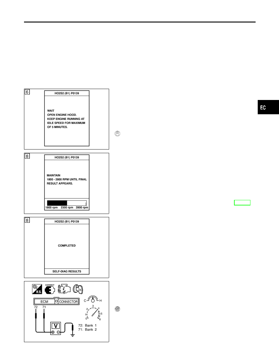
6)
Select “HO2S2 (B1) P0139” or “HO2S2 (B2) P0159” of
“HO2S2” in “DTC WORK SUPPORT” mode with CONSULT-II.
7)
Start engine and follow the instruction of CONSULT-II.
8)
Make sure that “OK” is displayed after touching “SELF-DIAG
RESULTS”.
If NG is displayed, refer to “Diagnostic Procedure”, EC-271.
If “CANNOT BE DIAGNOSED” is displayed, perform the fol-
lowing.
a)
Stop engine and cool down until “COOLAN TEMP/S” indicates
less than 70°C (158°F).
b)
Turn ignition switch “ON”.
c)
Select “DATA MONITOR” mode with CONSULT-II.
d)
Start engine.
e)
Return to step 6 again when the “COOLAN TEMP/S” reaches
to 70°C (158°F).
SEF312XB
Overall Function Check
NHEC0151
Use this procedure to check the overall function of the heated oxy-
gen sensor 2 (rear) circuit. During this check, a 1st trip DTC might
not be confirmed.
WITH GST
NHEC0151S01
1)
Start engine and drive vehicle at a speed of more than 70 km/h
(43 MPH) for 2 consecutive minutes.
2)
Stop vehicle with engine running.
3)
Set voltmeter probes between ECM terminal 72 [HO2S2 (B1)
signal] or 71 [HO2S2 (B2) signal] and engine ground.
GI
MA
EM
LC
FE
AT
AX
SU
BR
ST
RS
BT
HA
SC
EL
IDX
DTC P0139 (BANK 1), P0159 (BANK 2) HO2S2 (REAR) (RESPONSE
MONITORING)
Possible Cause
EC-267