Infiniti I30 (A33). Manual - part 223


  Index      Infiniti     Infiniti I30 (A33) - service repair manual 2001 year


Search            


Content   ..  221  222  223  224   ..


Infiniti I30 (A33). Manual - part 223


5

CHECK HEATED OXYGEN SENSOR 1 (FRONT)

With CONSULT-II

1. Start engine and warm it up to normal operating temperature.
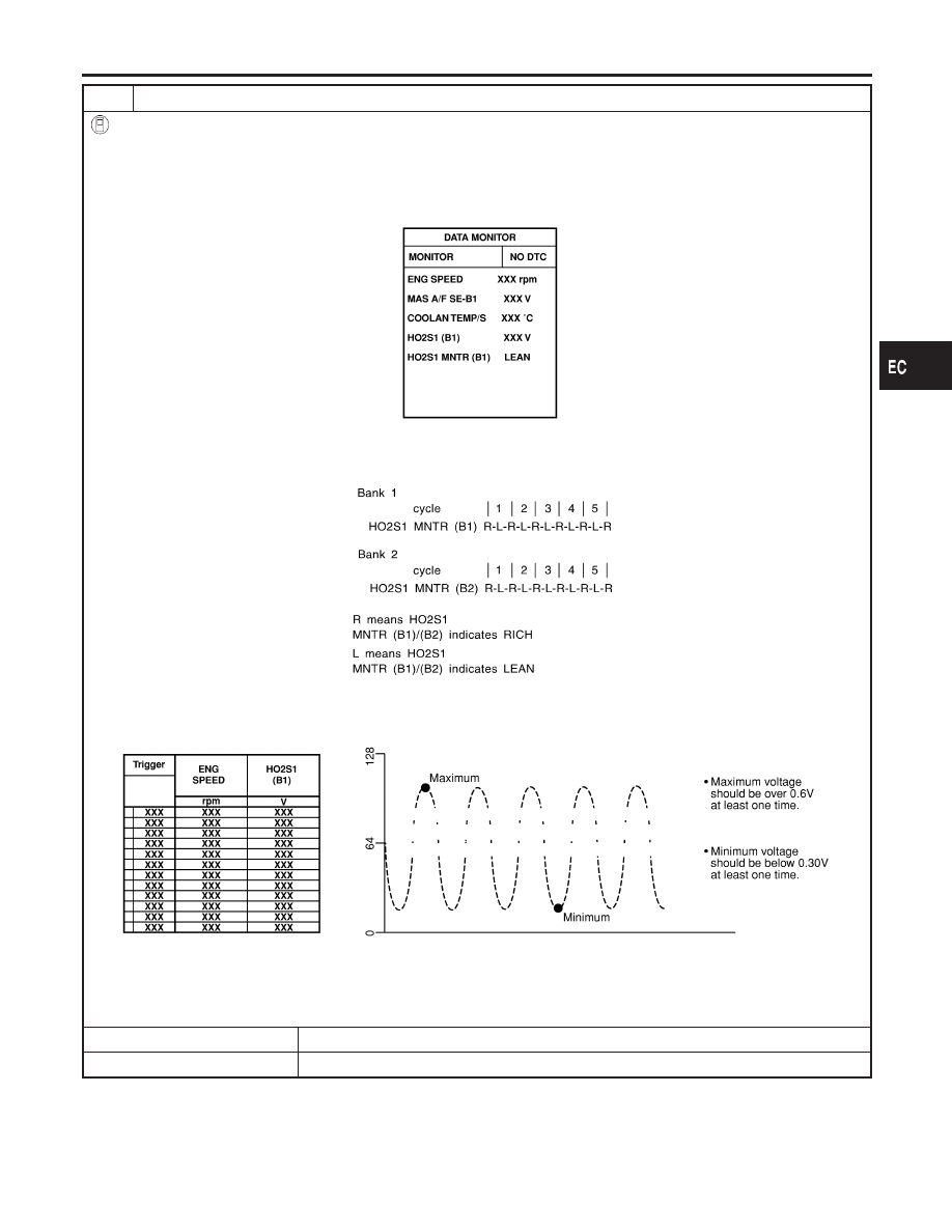
2. Select “MANU TRIG” and adjust “TRIGGER POINT” to 100% in “DATA MONITOR” mode with CONSULT-II.
3. Select “HO2S1 (B1)/(B2)” and “HO2S1 MNTR (B1)/(B2)”.
4. Hold engine speed at 2,000 rpm under no load during the following steps.
5. Touch “RECORD” on CONSULT-II screen.

SEF646Y

6. Check the following.

I

“HO2S1 MNTR (B1)/(B2)” in “DATA MONITOR” mode changes from “RICH” to “LEAN” to “RICH” 5 times in 10 seconds.
5 times (cycles) are counted as shown below.

SEF647Y

I

“HO2S1 (B1)/(B2)” voltage goes above 0.6V at least once.

I

“HO2S1 (B1)/(B2)” voltage goes below 0.3V at least once.

I

“HO2S1 (B1)/(B2)” voltage never exceeds 1.0V.

SEF648Y

CAUTION:

Discard any heated oxygen sensor which has been dropped from a height of more than 0.5 m (19.7 in) onto a
hard surface such as a concrete floor; use a new one.

OK or NG

OK

©

GO TO 8.

NG

©

GO TO 7.

GI

MA

EM

LC

FE

AT

AX

SU

BR

ST

RS

BT

HA

SC

EL

IDX

DTC P0131 (BANK 1), P0151 (BANK 2) HO2S1 (FRONT) (LEAN SHIFT

MONITORING)

Diagnostic Procedure (Cont’d)

EC-207

6

CHECK HEATED OXYGEN SENSOR 1 (FRONT)

Without CONSULT-II

1. Start engine and warm it up to normal operating temperature.
2. Set voltmeter probes between ECM terminal 63 [HO2S1 (B1) signal] or 62 [HO2S1 (B2) signal] and engine ground.
3. Check the following with engine speed held at 2,000 rpm constant under no load.

SEF967XA

CAUTION:

Discard any heated oxygen sensor which has been dropped from a height of more than 0.5 m (19.7 in) onto a
hard surface such as a concrete floor; use a new one.

OK or NG

OK

©

GO TO 8.

NG

©

GO TO 7.

7

REPLACE HEATED OXYGEN SENSOR 1 (FRONT)

1. Turn ignition switch “OFF”.
2. Check heated oxygen sensor 1 (front) harness protector color.

SEC020C

CAUTION:

Before installing new oxygen sensor, clean exhaust system threads using Oxygen Sensor Thread Cleaner tool
J-43897-18 or J-43897-12 and approved anti-seize lubricant.

©

Replace malfunctioning heated oxygen sensor 1 (front).

DTC P0131 (BANK 1), P0151 (BANK 2) HO2S1 (FRONT) (LEAN SHIFT

MONITORING)

Diagnostic Procedure (Cont’d)

EC-208

8

CHECK HO2S1 (FRONT) SHIELD CIRCUIT FOR OPEN AND SHORT

1. Turn ignition switch “OFF”.
2. Disconnect joint connector-17 or joint connector-18.
3. For circuit, refer to “Wiring Diagram”, EC-192.
4. Check the following.

I

Continuity between joint connector terminal 1 or 2 and ground

I

Joint connector
(Refer to EL-525, “HARNESS LAYOUT”.)

Continuity should exist.

5. Also check harness for short to power.
6. Then reconnect joint connector-17 or joint connector-18.

OK or NG

OK

©

GO TO 9.

NG

©

Repair open circuit or short to power in harness or connectors.

9

CHECK INTERMITTENT INCIDENT

Refer to “TROUBLE DIAGNOSIS FOR INTERMITTENT INCIDENT”, EC-144.
For circuit, refer to “Wiring Diagram”, EC-195.

©

INSPECTION END

GI

MA

EM

LC

FE

AT

AX

SU

BR

ST

RS

BT

HA

SC

EL

IDX

DTC P0131 (BANK 1), P0151 (BANK 2) HO2S1 (FRONT) (LEAN SHIFT

MONITORING)

Diagnostic Procedure (Cont’d)

EC-209

SEF463R

SEF288D

Component Description

NHEC0101

The heated oxygen sensor 1 (front) is placed into the front tube. It
detects the amount of oxygen in the exhaust gas compared to the
outside air. The heated oxygen sensor 1 (front) has a closed-end
tube made of ceramic zirconia. The zirconia generates voltage from
approximately 1V in richer conditions to 0V in leaner conditions.
The heated oxygen sensor 1 (front) signal is sent to the ECM. The
ECM adjusts the injection pulse duration to achieve the ideal air-
fuel ratio. The ideal air-fuel ratio occurs near the radical change
from 1V to 0V.

CONSULT-II Reference Value in Data Monitor
Mode

NHEC0102

Specification data are reference values.

MONITOR ITEM

CONDITION

SPECIFICATION

HO2S1 (B1)
HO2S1 (B2)

I

Engine: After warming up

Maintaining engine speed at 2,000
rpm

0 - 0.3V

+,

Approx. 0.6 - 1.0V

HO2S1 MNTR
(B1)
HO2S1 MNTR
(B2)

LEAN

+,

RICH

Changes more than 5 times during
10 seconds.

SEF299U

On Board Diagnosis Logic

NHEC0104

To judge the malfunction, the output from the heated oxygen sen-
sor 1 (front) is monitored to determine whether the “rich” output is
sufficiently high. The “lean” output is sufficiently low. When both the
outputs are shifting to the rich side, the malfunction will be
detected.
Malfunction is detected when the maximum and minimum voltages
from the sensor are beyond the specified voltages.

DTC P0132 (BANK 1), P0152 (BANK 2) HO2S1 (FRONT) (RICH SHIFT

MONITORING)

Component Description

EC-210


Content   ..  221  222  223  224   ..