Infiniti I30 (A33). Manual - part 81
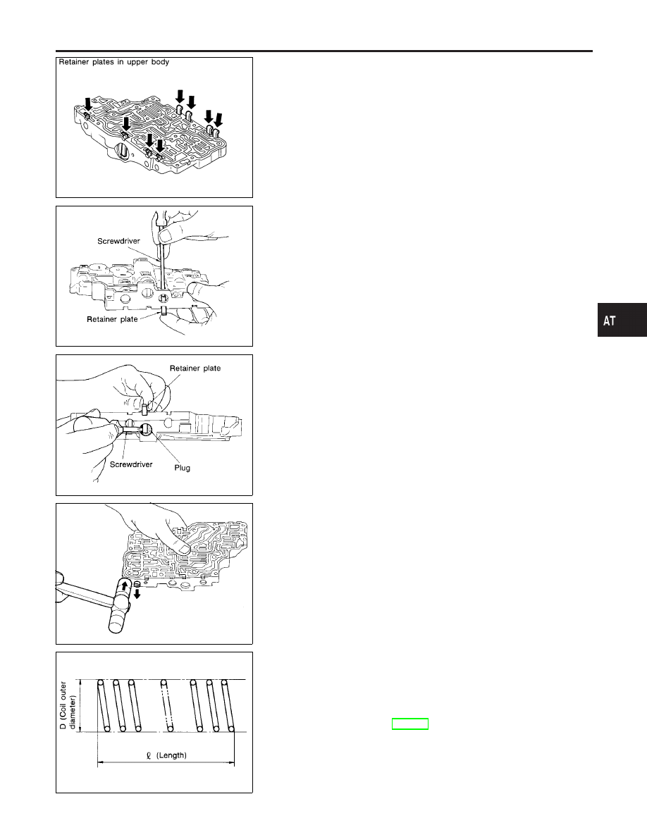
SAT551G
DISASSEMBLY
NHAT0138
1.
Remove valves at retainer plates.
I
Do not use a magnetic pick-up tool.
SAT553G
a.
Use a screwdriver to remove retainer plates.
SAT554G
b.
Remove retainer plates while holding spring, plugs or sleeves.
I
Remove plugs slowly to prevent internal parts from jump-
ing out.
SAT137D
c.
Place mating surface of valve body face down, and remove
internal parts.
I
If a valve is hard to remove, place valve body face down
and lightly tap it with a soft hammer.
I
Be careful not to drop or damage valves and sleeves.
SAT138D
INSPECTION
NHAT0139
Valve Spring
NHAT0139S01
I
Measure free length and outer diameter of each valve spring.
Also check for damage or deformation.
Inspection standard:
Refer to SDS, AT-383.
I
Replace valve springs if deformed or fatigued.
Control Valves
NHAT0139S02
I
Check sliding surfaces of valves, sleeves and plugs.
GI
MA
EM
LC
EC
FE
AX
SU
BR
ST
RS
BT
HA
SC
EL
IDX
REPAIR FOR COMPONENT PARTS
Control Valve Upper Body (Cont’d)
AT-321