Infiniti I30 (A33). Manual - part 35
Possible Cause
NHAT0220
Check the following items.
I
Shift solenoid valve A
I
Each clutch
I
Hydraulic control circuit
SAT014K
SAT971J
SAT021J
Diagnostic Trouble Code (DTC) Confirmation
Procedure
NHAT0221
CAUTION:
I
Always drive vehicle at a safe speed.
I
Be careful not to rev engine into the red zone on the
tachometer.
NOTE:
If “DTC Confirmation Procedure” has been previously conducted,
always turn ignition switch “OFF” and wait at least 5 seconds
before conducting the next test.
TESTING CONDITION:
Always drive vehicle on a level road to improve the accuracy
of test.
After the repair, perform the following procedure to confirm the
malfunction is eliminated.
WITH CONSULT-II
NHAT0221S01
1)
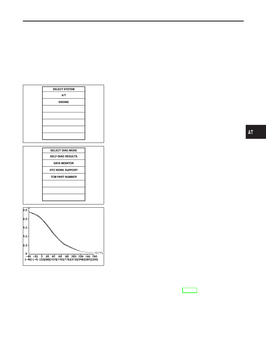
Start engine and select “DATA MONITOR” mode for “A/T” with
CONSULT-II.
2)
Make sure that output voltage of A/T fluid temperature sensor
is within the range below.
FLUID TEMP SEN: 0.4 - 1.5V
If out of range, drive the vehicle to decrease the voltage (warm
up the fluid) or stop engine to increase the voltage (cool down
the fluid).
3)
Select “3RD GR FNCTN P0733” of “DTC WORK SUPPORT”
mode for “A/T” with CONSULT-II and touch “START”.
4)
Accelerate vehicle to 80 to 95 km/h (50 to 59 MPH) under the
following condition and release the accelerator pedal com-
pletely.
THROTTLE POSI: Less than 1.0/8 (at all times during step
4)
Selector lever: D position (OD “ON”)
I
Check that “GEAR” shows “4” after releasing pedal.
5)
Depress accelerator pedal steadily with 3.5/8 - 4.5/8 of
“THROTTLE POSI” from a speed of 80 to 95 km/h (50 to 59
MPH) until “TESTING” changes to “STOP VEHICLE” or “COM-
PLETED”. (It will take approximately 3 seconds.)
If the check result NG appears on CONSULT-II screen, go to
“DIAGNOSTIC PROCEDURE”, AT-140.
If “STOP VEHICLE” appears on CONSULT-II screen, go to
following step.
I
Check that “GEAR” shows “3” when depressing accelera-
tor pedal with 3.5/8 - 4.5/8 of “THROTTLE POSI”.
I
If “TESTING” does not appear on CONSULT-II for a long
time, select “SELF-DIAG RESULTS” for “ENGINE”. In case
GI
MA
EM
LC
EC
FE
AX
SU
BR
ST
RS
BT
HA
SC
EL
IDX
DTC P0733 A/T 3RD GEAR FUNCTION
Possible Cause
AT-137