Infiniti I30 (A33). Manual - part 26
 

  Index      Infiniti     Infiniti I30 (A33) - service repair manual 2001 year


Search            


Content   ..  24  25  26  27   ..


Infiniti I30 (A33). Manual - part 26


2

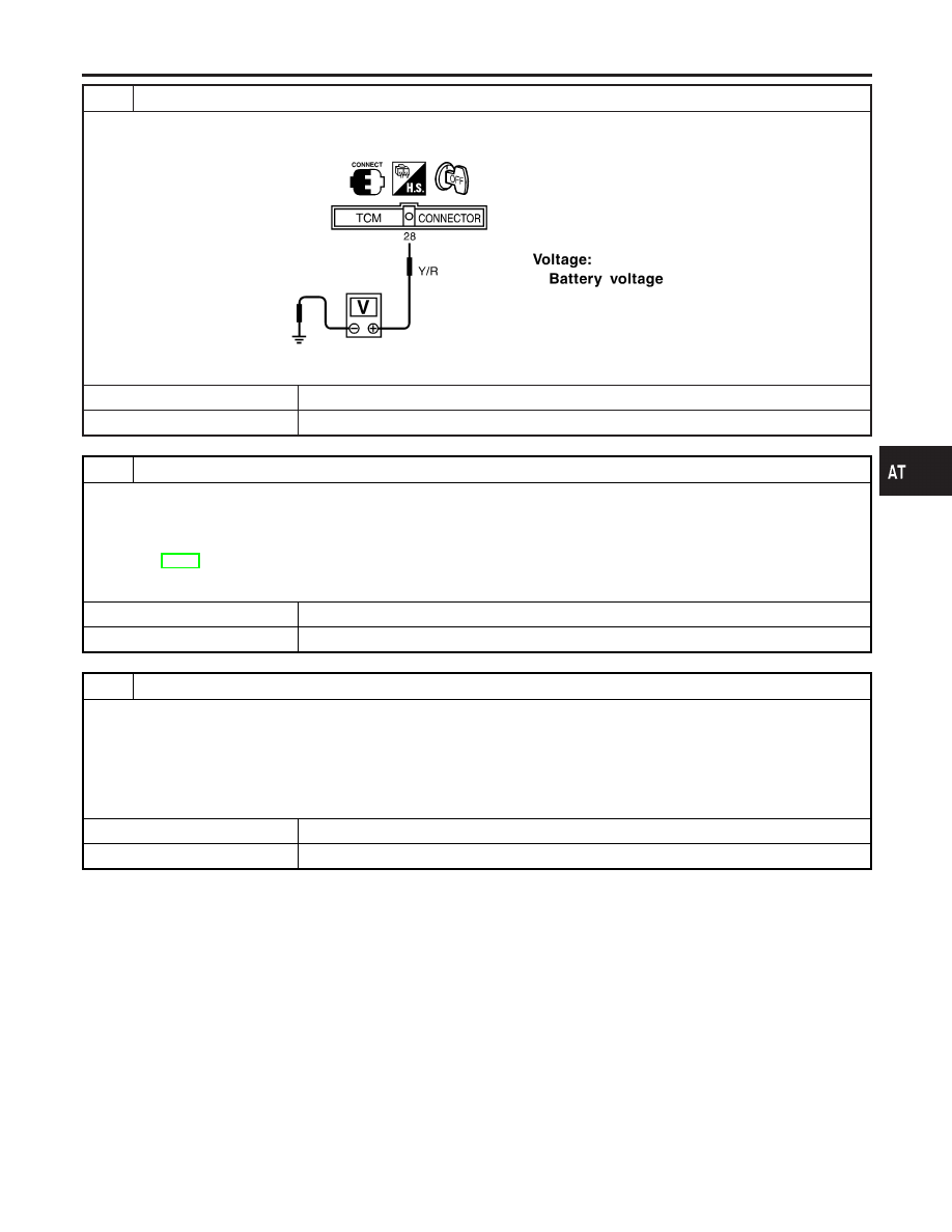
CHECK TCM POWER SOURCE STEP 2

1. Turn ignition switch to OFF position.
2. Check voltage between TCM terminal 28 and ground.

SAT612J

OK or NG

OK

©

GO TO 4.

NG

©

GO TO 3.

3

DETECT MALFUNCTIONING ITEM

Check the following items:

I

Harness for short or open between ignition switch and TCM terminals 10, 19 and 28 (Main harness)

I

Fuse

I

Ignition switch
Refer to EL-10, “POWER SUPPLY ROUTING”.

OK or NG

OK

©

GO TO 4.

NG

©

Repair or replace damaged parts.

4

CHECK TCM GROUND CIRCUIT

1. Turn ignition switch to OFF position.
2. Disconnect TCM harness connector.
3. Check continuity between TCM terminals 25, 48 and ground. Refer to wiring diagram — AT — MAIN.

Continuity should exist.

If OK, check harness for short to ground and short to power.

OK or NG

OK

©

INSPECTION END

NG

©

Repair open circuit or short to ground or short to power in harness or connectors.

GI

MA

EM

LC

EC

FE

AX

SU

BR

ST

RS

BT

HA

SC

EL

IDX

TROUBLE DIAGNOSIS FOR POWER SUPPLY

Diagnostic Procedure (Cont’d)

AT-101

SAT644J

Description

NHAT0034

I

The park/neutral position (PNP) switch includes a transmission
range switch.

I

The transmission range switch detects the selector lever posi-
tion and sends a signal to the TCM.

TCM TERMINALS AND REFERENCE VALUE

NHAT0034S01

Remarks: Specification data are reference values.

Terminal

No.

Wire color

Item

Condition

Judgement

standard

(Approx.)

26

PU/W

PNP switch 1 posi-
tion

When setting selector lever to 1 position.

Battery volt-
age

When setting selector lever to other positions. 0V

27

P/B

PNP switch 2 posi-
tion

When setting selector lever to 2 position.

Battery volt-
age

When setting selector lever to other positions. 0V

34

Y/PU

PNP switch D posi-
tion

When setting selector lever to D position.

Battery volt-
age

When setting selector lever to other positions. 0V

35

G/W

PNP switch R posi-
tion

When setting selector lever to R position.

Battery volt-
age

When setting selector lever to other positions. 0V

36

R/G

PNP switch P or N
position

When setting selector lever to P or N posi-
tion.

Battery volt-
age

When setting selector lever to other positions. 0V

On Board Diagnosis Logic

NHAT0201

Diagnostic trouble code PNP SW/CIRC with CONSULT-II or P0705
without CONSULT-II is detected when TCM does not receive the
correct voltage signal from the switch based on the gear position.

DTC P0705 PARK/NEUTRAL POSITION SWITCH

Description

AT-102

Possible Cause

NHAT0202

Check the following items.

I

Harness or connectors
(The park/neutral position (PNP) switch circuit is open or
shorted.)

I

Park/neutral position (PNP) switch

SAT014K

Diagnostic Trouble Code (DTC) Confirmation
Procedure

NHAT0203

CAUTION:

Always drive vehicle at a safe speed.
NOTE:
If “DTC Confirmation Procedure” has been previously conducted,
always turn ignition switch OFF and wait at least 5 seconds before
conducting the next test.
After the repair, perform the following procedure to confirm the
malfunction is eliminated.

SEF949Y

WITH CONSULT-II

NHAT0203S01

1)

Turn ignition switch ON.

2)

Select “DATA MONITOR” mode for “ENGINE” with CONSULT-
II.

3)

Start engine and maintain the following conditions for at least
5 consecutive seconds.
VHCL SPEED SE: 10 km/h (6 MPH) or more
THRTL POS SEN: More than 1.3V
Selector lever: D position (O/D ON or OFF)

WITH GST

NHAT0203S02

Follow the procedure “With CONSULT-II”.

GI

MA

EM

LC

EC

FE

AX

SU

BR

ST

RS

BT

HA

SC

EL

IDX

DTC P0705 PARK/NEUTRAL POSITION SWITCH

Possible Cause

AT-103

Wiring Diagram — AT — PNP/SW

NHAT0035

MAT054B

SAT293K

DTC P0705 PARK/NEUTRAL POSITION SWITCH

Wiring Diagram — AT — PNP/SW

AT-104


Content   ..  24  25  26  27   ..