Infiniti G37 Coupe. Manual - part 751


  Index      Infiniti     Infiniti G37 Coupe - service repair manual 2008 year


Search            


Content   ..  749  750  751  752   ..


Infiniti G37 Coupe. Manual - part 751


HA-50

< ON-VEHICLE REPAIR >

CONDENSER PIPE ASSEMBLY
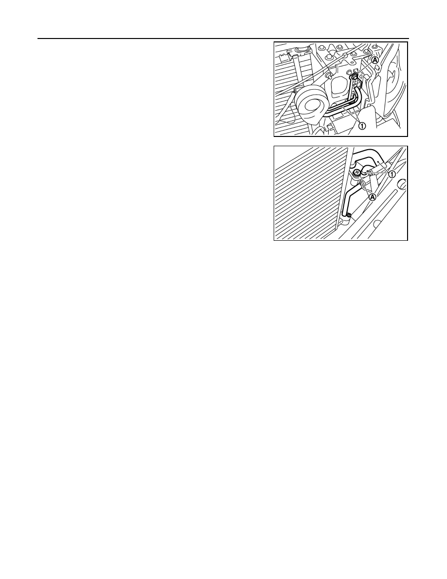
6.

Remove mounting bolt (A) from condenser pipe assembly (1).

7.

Remove mounting bolt (A) from condenser pipe assembly (1).

8.

Remove condenser pipe assembly.

INSTALLATION

Installation is basically the reverse order of removal.

CAUTION:

• Replace O-rings with new ones. Then apply compressor oil to them when installing.
• Female-side piping connection is thin and easy to deform. Slowly insert the male-side piping

straight in axial direction.

• Insert piping securely until a click is heard.
• After piping connection is completed, pull male-side piping by hand to make sure that connection

does not come loose.

• Check for leakages when recharging refrigerant.

JSIIA0088ZZ

JSIIA0030ZZ

LIQUID TANK

HA-51

< ON-VEHICLE REPAIR >

C

D

E

F

G

H

J

K

L

M

A

B

HA

N

O

P

LIQUID TANK

Exploded View

INFOID:0000000001713752

Removal and Installation

INFOID:0000000001675650

REMOVAL

1.

Use a refrigerant collecting equipment (for HFC-134a) to discharge the refrigerant.

2.

Remove front grille. Refer to 

EXT-19, "Exploded View"

.

3.

Clean liquid tank and its surrounding area. Then remove dust and rust from liquid tank.

CAUTION:

Be sure to clean carefully.

4.

Remove mounting bolts (A) from liquid tank (1).

5.

Remove liquid tank.

INSTALLATION

 Install liquid tank, and then install liquid tank bracket on condenser. 

CAUTION:

• Check that liquid tank bracket is securely installed at protrusion of condenser. (Check that liquid

tank bracket does not move to a position below center of liquid tank.)

• Replace O-rings of the A/C piping with new ones. Then apply compressor oil to them when installing.
• Check for leakages when recharging refrigerant.

1.

Refrigerant pressure sensor

2.

O-ring

3.

Liquid tank bracket

4.

Liquid tank

5.

Bracket

6.

Condenser pipe assembly

7.

Radiator & condenser assembly

Refer to 

GI-4, "Components"

 for symbols in the figure.

JSIIA0012GB

JSIIA0094ZZ

HA-52

< ON-VEHICLE REPAIR >

REFRIGERANT PRESSURE SENSOR

REFRIGERANT PRESSURE SENSOR

Exploded View

INFOID:0000000001713754

Removal and Installation

INFOID:0000000001675652

REMOVAL

1.

Remove liquid tank. Refer to 

HA-51, "Exploded View"

.

2.

Fix the liquid tank (1) with a vise (A). Remove the refrigerant
pressure sensor (2) with a wrench (B).

CAUTION:

Be careful not to damage liquid tank.

INSTALLATION

Installation is basically the reverse order of removal.

CAUTION:

• Apply compressor oil to O-ring of refrigerant pressure sensor when installing.
• Check for leakages when recharging refrigerant.

1.

Refrigerant pressure sensor

2.

O-ring

3.

Liquid tank bracket

4.

Liquid tank

5.

Bracket

6.

Condenser pipe assembly

7.

Radiator & condenser assembly

Refer to 

GI-4, "Components"

 for symbols in the figure.

JSIIA0012GB

JSIIA0075ZZ

EVAPORATOR

HA-53

< ON-VEHICLE REPAIR >

C

D

E

F

G

H

J

K

L

M

A

B

HA

N

O

P

EVAPORATOR

Exploded View

INFOID:0000000001713757

1.

Aspirator

2.

Aspirator hose

3.

Front heater duct

4.

Foot duct (left)

5.

Defroster seal

6.

Packing

7.

Ventilator seal

8.

Ventilator door

9.

Foot duct (right)

10.

Defroster door lever

11.

Foot door lever

12. Ventilator door lever

13.

Ventilator door link

14.

Main link

15. Mode door motor bracket

16.

Mode door motor

17.

Air mix door motor (passenger side)

18. Intake sensor

19.

Intake sensor bracket

20.

O-ring

21. Low-pressure pipe 1

22.

High-pressure pipe 2

23.

Expansion valve

24. Cooler pipe grommet

25.

Insulator

26.

Evaporator cover adapter

27. Heater pipe bracket

28.

Case rubber

29.

Case packing

30. Heater & cooling unit case (left)

31.

Heater pipe grommet

32.

Heater core

33. Air mix door motor (driver side)

*

34.

Foot door (left)

35.

Rear ventilator door

36. Foot door (right)

JSIIA0863GB


Content   ..  749  750  751  752   ..