Infiniti G35 (V35) Sedan. Manual - part 387


  Index      Infiniti     Infiniti G35 (V35) Sedan - service repair manual 2007 year


Search            


Content   ..  385  386  387  388   ..


Infiniti G35 (V35) Sedan. Manual - part 387


DOOR LOCK

DLK-209

< ON-VEHICLE REPAIR >

[INTELLIGENT KEY SYSTEM]

C

D

E

F

G

H

I

J

L

M

A

B

DLK

N

O

P

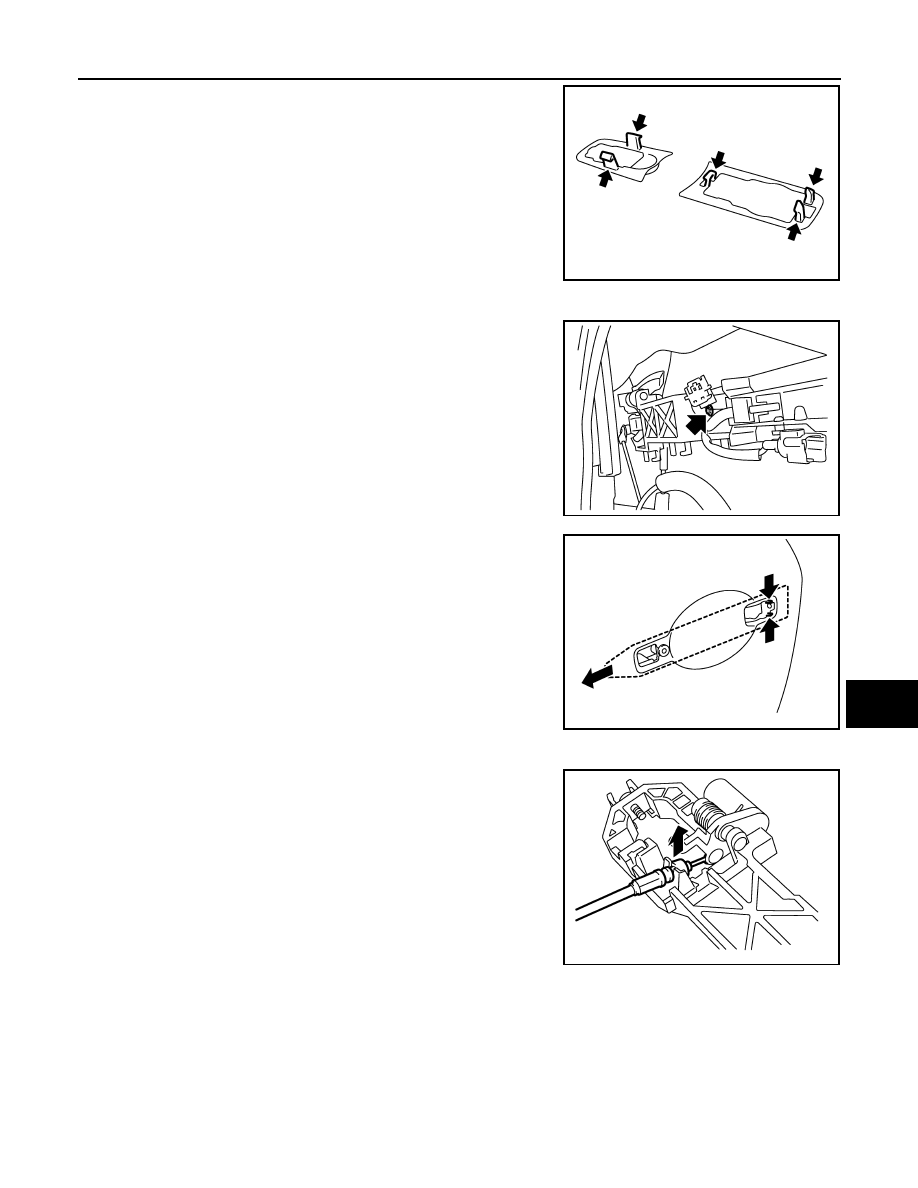
11. Remove the front gasket and rear gasket.

12. Remove the TORX bolts (T30), and remove the door lock assembly.
13. Remove the TORX bolt (T30) of the outside handle bracket.

14. While pulling outside handle bracket, slide toward rear of vehicle

to remove outside handle bracket.

15. Disconnect the door lock actuator connector and remove the door lock assembly.
16. Reach in to separate the outside handle cable connection.

INSTALLATION

Install in the reverse order of removal.

CAUTION:

To install each rod, rotate the rod holder until a click is felt.

REAR DOOR LOCK

REAR DOOR LOCK : Exploded View

INFOID:0000000000961279

PIIB5811E

JMKIA0022ZZ

PIIB5814E

PIIB5815E

DLK-210

< ON-VEHICLE REPAIR >

[INTELLIGENT KEY SYSTEM]

DOOR LOCK

REAR DOOR LOCK : Removal and Installation

INFOID:0000000000961280

REMOVAL

1.

Remove the rear door finisher. Refer to 

INT-10, "Removal and Installation"

.

2.

Disconnect the inside handle knob cable and lock knob cable
from the back side of the rear door finisher.

3.

Remove the rear door glass. Refer to 

GW-19, "Removal and Installation"

.

4.

Remove door side grommet, and remove outside handle escutcheon bolt (TORX T30) from grommet
hole.

CAUTION:

1.

Inside handle cap

2.

Inside handle

3.

Outside handle escutcheon

4.

Outside handle

5.

Rear gasket

6.

Front gasket

7.

Outside handle bracket

8.

Door lock assembly

9.

Striker

10. Seal

11.

Lock knob cable

12. Inside handle knob cable

13. Outside handle cable

Refer to 

GI-4, "Components"

 for symbols in the figure.

JMKIA0023GB

JMKIA0024ZZ

DOOR LOCK

DLK-211

< ON-VEHICLE REPAIR >

[INTELLIGENT KEY SYSTEM]

C

D

E

F

G

H

I

J

L

M

A

B

DLK

N

O

P

Do not forcibly remove the TORX bolts (T30).

5.

While pulling the outside handle, remove outside handle
escutcheon.

6.

While pulling outside handle, slide toward rear of vehicle to
remove outside handle.

7.

Remove the front gasket and rear gasket.

8.

Remove the TORX bolts (T30), remove the door lock assembly.

JMKIA0025ZZ

PIIB5809E

PIIB5810E

PIIB5811E

DLK-212

< ON-VEHICLE REPAIR >

[INTELLIGENT KEY SYSTEM]

DOOR LOCK

9.

Remove the TORX bolt (T30), and remove the outside handle
bracket.

10. While pulling outside handle, slide toward rear of vehicle to

remove outside handle.

11. Disconnect the door lock actuator connector and remove the door lock assembly.

12. Reach in to separate outside handle cable connection.

INSTALLATION

Install in the reverse order of removal.

CAUTION:

To install each rod, rotate the rod holder until a click is felt.

JMKIA0026ZZ

PIIB5814E

PIIB5815E


Content   ..  385  386  387  388   ..