Infiniti G35 (V35). Manual - part 744


  Index      Infiniti     Infiniti G35 (V35) Coupe - service repair manual 2007 year


Search            


Content   ..  742  743  744  745   ..


Infiniti G35 (V35). Manual - part 744


SE-78

AUTOMATIC DRIVE POSITIONER

Check UART Communication Line Circuit 

NIS001IG

1. 

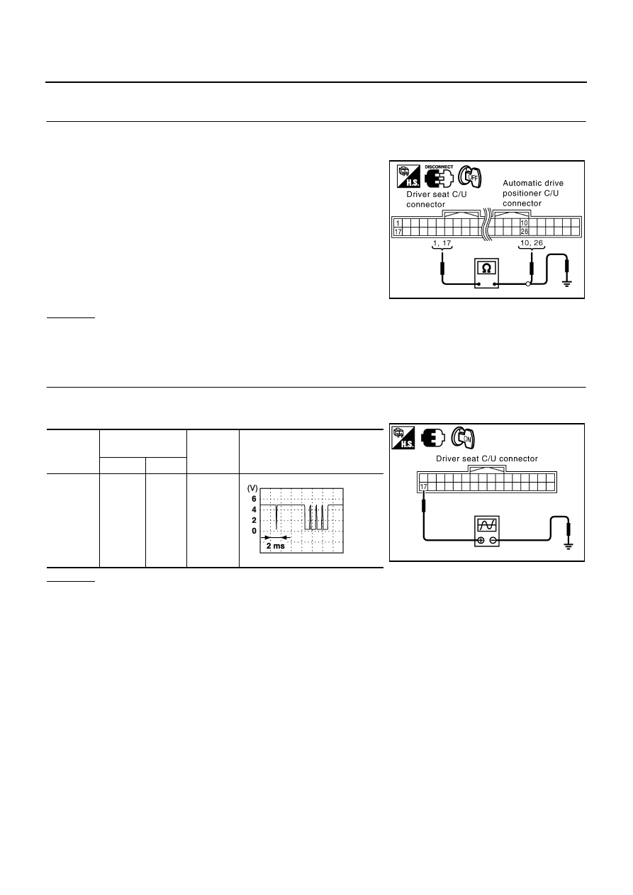
CHECK UART LINE HERNESS

1.

Turn ignition switch OFF.

2.

Disconnect driver seat control unit connector and automatic drive positioner control unit connector.

3.

Check continuity between driver seat control unit connector
B352 terminal 1, 17 and automatic drive positioner connector
M96 terminal 10, 26.

4.

Check continuity between driver seat control unit connector
B352 terminal 1, 17 and ground.

OK or NG

OK

>> GO TO 2.

NG

>> Repair or replace harness between driver seat control unit and automatic drive positioner control

unit.

2. 

CHECK UART LINE SIGNAL 1

1.

Turn ignition switch ON.

2.

Check signal between driver seat control unit connector ground, with oscilloscope.

OK or NG

OK

>> GO TO 3.

NG

>> Check the flowing.

When voltage signal does not appear with a constant voltage (approx. 5V), replace driver seat
control unit.

When voltage signal does not appear with a constant voltage (approx. 0V), replace automatic
drive positioner control unit.

17 (R/Y) 

 26 (R/G)

: Continuity should exist.

1 (L/W) 

 10 (R/L)

: Continuity should exist.

17 (R/Y) 

 Ground

: Continuity should not exist.

1 (L/W) 

 Ground

: Continuity should not exist.

PIIB3418E

Connector

Terminals 

(Wire color)

Condition

Signal

(Reference value)

(+)

(–)

B352

17 (R/Y)

Ground

Seat 
memory 
switch 1 or 
2 opera-
tion

PIIB7644E

PIIA4814E

AUTOMATIC DRIVE POSITIONER

SE-79

C

D

E

F

G

H

J

K

L

M

A

B

SE

3. 

CHECK UART LINE SIGNAL 2

Check signal between automatic driver positioner control unit connector ground, with oscilloscope.

OK or NG

OK

>> GO TO 4.

NG

>> Check the flowing.

When voltage signal does not appear with a constant voltage (approx. 5V), replace automatic
driver seat control unit.

When voltage signal does not appear with a constant voltage (approx. 0V), replace driver seat
control unit.

4. 

CHECK DRIVER SEAT CONTROL UNIT

Dose the automatic drive positioner operate, when the driver control unit exchanged?

Does seat memory function operate?

YES

>> Replace automatic drive positioner control unit.

NG

>> Replace driver seat control unit. 

Check Sliding Limit Switch Signal

NIS001IK

1. 

CHECK SLIDING LIMIT SWITCH SIGNAL

When operation condition consists, check voltage between driver seat control unit connector B352 terminal 4
and ground.

OK or NG

OK

>> Sliding limit switch (forward) signal is OK.

NG

>> GO TO 2. 

Connector

Terminals 

(Wire color)

Condition

Signal

(Reference value)

(+)

(–)

M96

10 (R/Y)

Ground

Seat 
memory 
switch 1 or 
2 opera-
tion

PIIB7645E

PIIA4813E

Connector

Terminals

Condition

Voltage (V)

(Approx.)

(+)

(-)

B352

4 (OR)

Ground

The seat slide front most part

0

Other than above

5

PIIB7375E

SE-80

AUTOMATIC DRIVE POSITIONER

2. 

CHECK HARNESS CONTINUITY

1.

Disconnect driver seat control unit and sliding limit switch connector.

2.

Check continuity between driver seat control unit connector
B352 terminal 4 and sliding limit switch connector B329 terminal
1.

OK or NG

OK

>> GO TO 3.

NG

>> Repair or replace harness between driver seat control

unit and sliding limit switch.

3. 

CHECK SLIDING LIMIT SWITCH CIRCUIT

Check continuity between sliding limit switch connector B329 termi-
nal 2 and ground.

OK or NG

OK

>> GO TO 4.

NG

>> Repair or replace harness.

4. 

CHECK SLIDING LIMIT SWITCH

Check continuity between sliding limit switch connector B329 termi-
nals 1 and 2.

OK or NG

OK

>> Check the condition of the harness and the connector.

NG

>> Replace sliding limit switch.

Check Seatback Switch Signal

NIS001IL

1. 

CHECK SEATBACK SWITCH SIGNAL

Check voltage between driver seat control unit connector B353 ter-
minal 41 and ground.

OK or NG

OK 

>> Seatback switch signal is OK.

NG

>>  GO TO 2.

4 (OR) - 1 (OR)

: Continuity should exist.

PIIB7376E

2 (B) - Ground

: Continuity should exist.

PIIB4558E

Connector

Terminal

Condition

Continuity

B329

1

2

When sliding limit switch fully front

Yes

Other than above

No

PIIB4559E

Connector

Terminal

Condition

Voltage (V)

(Approx.)

(+)

(–)

B353

41 (L)

Ground

Seatback fold down

0

Other than above

5

PIIB7377E

AUTOMATIC DRIVE POSITIONER

SE-81

C

D

E

F

G

H

J

K

L

M

A

B

SE

2. 

CHECK HARNESS CONTINUITY

1.

Disconnect driver seat control unit and seatback switch connector.

2.

Check continuity between driver seat control unit connector
B353 terminal 41 and seatback switch connector B348 terminal
1.

OK or NG

OK

>> GO TO 3.

NG 

>> Repair or replace harness between driver seat control

unit and seatback switch.

3. 

CHECK SEATBACK SWITCH CIRCUIT

Check continuity between seatback switch connector B348 terminal
2 and ground.

OK or NG

OK >> GO 

TO 

4.

NG

>> Repair or replace harness.

4. 

CHECK SEATBACK SWITCH

Check continuity between seatback switch connector B348 terminals
1 and 2.

OK or NG

OK

>> Check the condition of the harness and the connector.

NG

>> Replace seatback switch.

Check Power Walk-in Switch Signal

NIS001IM

1. 

CHECK POWER WALK-IN SWITCH SIGNAL

Check voltage between driver seat control unit connector B353 ter-
minal 34and ground.

OK or NG

OK

>> Power walk-in switch signal is OK.

NG

>> GO TO 2.

41 (L) - 1 (L)

: Continuity should exist.

PIIB7378E

2 (B) - Ground

: Continuity should exist.

PIIB4561E

Connector

Terminal

Condition

Continuity

B348

1

2

When seatback switch forward

Yes

Other than above

No

PIIB4562E

Connector

Terminal

Condition

Voltage (V)

(Approx.)

(+)

(–)

B353

34 (G)

Ground

When power walk-in switch ON

0

Other than above

5

PIIB7379E


Content   ..  742  743  744  745   ..