Infiniti G35 (V35). Manual - part 737
SE-50
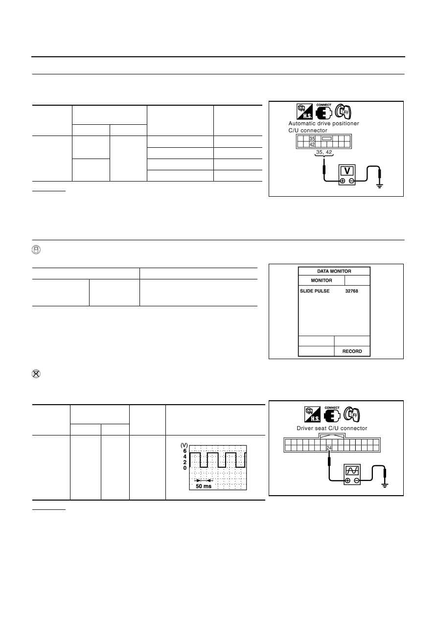
AUTOMATIC DRIVE POSITIONER
4.
CHECK BCM OUTPUT SIGNAL
1.
Connect automatic drive positioner control unit connector and tilt and telescopic motor connector.
2.
Tilt switch operate, check voltage between automatic drive positioner control unit connector and ground.
OK or NG
OK
>> Replace tilt and telescopic motor.
NG
>> Replace automatic drive positioner control unit.
Check Sliding Sensor Circuit
NIS001HT
1.
CHECK FUNCTION
With CONSULT-II
Check operation with “SLIDE PULSE” on the DATA MONITOR to make sure the pulse changes.
Without CONSULT-II
1.
Turn ignition switch OFF.
2.
Check signal between driver seat control unit connector and ground, with oscilloscope.
OK or NG
OK
>> Sliding sensor circuit is OK.
NG
>> GO TO 2.
Connector
Terminals
(Wire color)
Tilt switch condition
Voltage (V)
(Approx.)
(+)
(–)
M97
35 (G/Y)
Ground
UP
Battery voltage
Other than above
0
42 (G/W)
DOWN
Battery voltage
Other than above
0
PIIA5067E
Monitor item [OPERATION or UNIT]
Contents
SLIDE PULSE
—
The seat sliding position (pulse) judged
from the sliding sensor signal is dis-
played.
PIIB2040E
Connector
Terminals
(Wire color)
Condition
Signal
(Reference value)
(+)
(–)
B352
24 (R)
Ground
Sliding
motor
operation
PIIA4556E
PIIA3277E