Infiniti G35 (V35). Manual - part 597


  Index      Infiniti     Infiniti G35 (V35) Coupe - service repair manual 2007 year


Search            


Content   ..  595  596  597  598   ..


Infiniti G35 (V35). Manual - part 597


LT-68

FRONT FOG LAMP

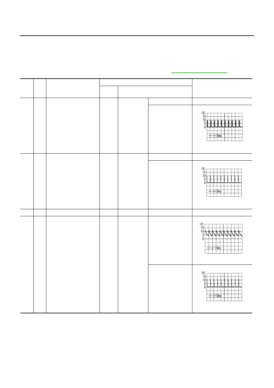
Terminals and Reference Values for BCM

NKS002OC

CAUTION:

Check combination switch system terminal waveform under the loaded condition with lighting
switch, turn signal switch and wiper switch OFF not to be fluctuated by overloaded.

Turn wiper dial position to 4 except when checking waveform or voltage of wiper dial position.
Wiper dial position can be confirmed on CONSULT-II. Refer to 

LT-17, "DATA MONITOR"

 .

Ter-

minal 

No.

Wire 

color

Signal name

Measuring condition

Reference value

Ignition 

switch

Operation or condition

2

G/R

Combination switch input 5

ON

Lighting, turn, 
wiper switch
(Wiper intermit-
tent dial posi-
tion 4)

OFF

Approx. 0 V

Lighting switch 2ND

Approx. 2.0 V

3

G

Combination switch input 4

ON

Lighting, turn, 
wiper switch
(Wiper intermit-
tent dial posi-
tion 4)

OFF

Approx. 0 V

Any of the conditions 
below

Lighting switch 2ND

Front fog lamp 
switch (Operates 
only front fog lamp 
switch)

Approx. 0.8 V

11

LG

Ignition switch (ACC)

ACC

Battery voltage

32

GY

Combination switch output 5

ON

Lighting, turn, 
wiper switch 
(Wiper intermit-
tent dial posi-
tion 4)

OFF

Approx. 7.2 V

Front fog lamp switch 
(Operates only front 
fog lamp switch)

Approx. 1.0 V

PKIB4953J

PKIB4955J

PKIB4960J

PKIB4956J

FRONT FOG LAMP

LT-69

C

D

E

F

G

H

I

J

L

M

A

B

LT

34

PU

Combination switch output 3

ON

Lighting, turn, 
wiper switch 
(Wiper intermit-
tent dial posi-
tion 4)

OFF

Approx. 7.2 V

Lighting switch 2ND

Approx. 1.2 V

35

Y/R

Combination switch output 2

ON

Lighting, turn, 
wiper switch
(Wiper intermit-
tent dial posi-
tion 4)

OFF

Approx. 7.2 V

Lighting switch 2ND

Approx. 1.2 V

38

W/L

Ignition switch (ON) 

ON

Battery voltage

39

L

CAN 


H

40

P

CAN 


L

42

GY

Battery power supply

OFF

Battery voltage

52

B

Ground

ON

Approx. 0 V

55

R

Battery power supply

OFF

Battery voltage

Ter-

minal 

No.

Wire 

color

Signal name

Measuring condition

Reference value

Ignition 

switch

Operation or condition

PKIB4960J

PKIB4958J

PKIB4960J

PKIB4958J

LT-70

FRONT FOG LAMP

Terminals and Reference Values for IPDM E/R

NKS002OD

How to Proceed With Trouble Diagnosis

NKS002OE

1.

Confirm the symptom or customer complaint.

2.

Understand operation description and function description. Refer to 

LT-64, "System Description"

 .

3.

Perform the Preliminary Check. Refer to 

LT-70, "Preliminary Check"

 .

4.

Check symptom and repair or replace the malfunctioning parts.

5.

Does the front fog lamp operate normally? If YES, GO TO 6. If NO, GO TO 4.

6.

INSPECTION END

Preliminary Check

NKS002OF

CHECK POWER SUPPLY AND GROUND CIRCUIT

1. 

CHECK FUSES AND FUSIBLE LINK

Check for blown fuses and fusible link.

Refer to 

LT-66, "Wiring Diagram — F/FOG —"

 .

OK or NG

OK

>> GO TO 2.

NG

>> If fuse or fusible link is blown, be sure to eliminate cause of malfunction before installing new fuse

or fusible link. Refer to 

PG-3, "POWER SUPPLY ROUTING CIRCUIT"

 .

Terminal 

No.

Wire 

color

Signal name

Measuring condition

Reference value

Ignition 

switch

Operation or condition

36

W/G

Front fog lamp (RH) 

ON

Lighting switch must be in the 2ND posi-
tion or AUTO position (headlamp is ON) 
and the front fog lamp switch must be ON

OFF

Approx. 0 V

ON

Battery voltage

37

SB

Front fog lamp (LH)

OFF

Approx. 0 V

ON

Battery voltage

38

B/R

Ground

ON

Approx. 0 V

48

L

CAN 


H

49

P

CAN 


L

60

B/R

Ground

ON

Approx. 0 V

Unit

Power source

Fuse and fusible link No.

BCM

Battery

F

18

Ignition switch ON or START position

1

Ignition switch ACC or ON position

6

IPDM E/R

Battery

88

FRONT FOG LAMP

LT-71

C

D

E

F

G

H

I

J

L

M

A

B

LT

2. 

CHECK POWER SUPPLY CIRCUIT 

1.

Turn ignition switch OFF.

2.

Disconnect BCM connector.

3.

Check voltage between BCM harness connector and ground.

OK or NG

OK

>> GO TO 3.

NG

>> Repair harness or connector.

3. 

CHECK GROUND CIRCUIT

Check continuity between BCM harness connector and ground.

OK or NG

OK

>> INSPECTION END

NG

>> Repair harness or connector.

CONSULT-II Functions (BCM)

NKS002OG

Refer to 

LT-16, "CONSULT-II Functions (BCM)"

 .

CONSULT-II Functions (IPDM E/R)

NKS002OH

Refer to 

LT-18, "CONSULT-II Functions (IPDM E/R)"

 .

(+)

(

)

Ignition switch position

OFF

ACC

ON

BCM

connector

Terminal 

M1

11

Ground

Approx. 0 V

Battery 
voltage

Battery 
voltage

38

Approx. 0 V

Approx. 0 V

Battery 
voltage

M2

42

Battery 
voltage

Battery 
voltage

Battery 
voltage

55

Battery 
voltage

Battery 
voltage

Battery 
voltage

PKIA5204E

BCM

connector

Terminal

Ground

Continuity

M2

52

Yes

PKIA6256E


Content   ..  595  596  597  598   ..