Infiniti G35 (V35). Manual - part 495


  Index      Infiniti     Infiniti G35 (V35) Coupe - service repair manual 2007 year


Search            


Content   ..  493  494  495  496   ..


Infiniti G35 (V35). Manual - part 495


ENGINE ASSEMBLY

EM-135

C

D

E

F

G

H

I

J

K

L

M

A

EM

For a location with a positioning pin, insert it securely into hole of
mating part.

For a part with a specified installation orientation, refer to com-
ponent figure in 

EM-131, "Components"

 .

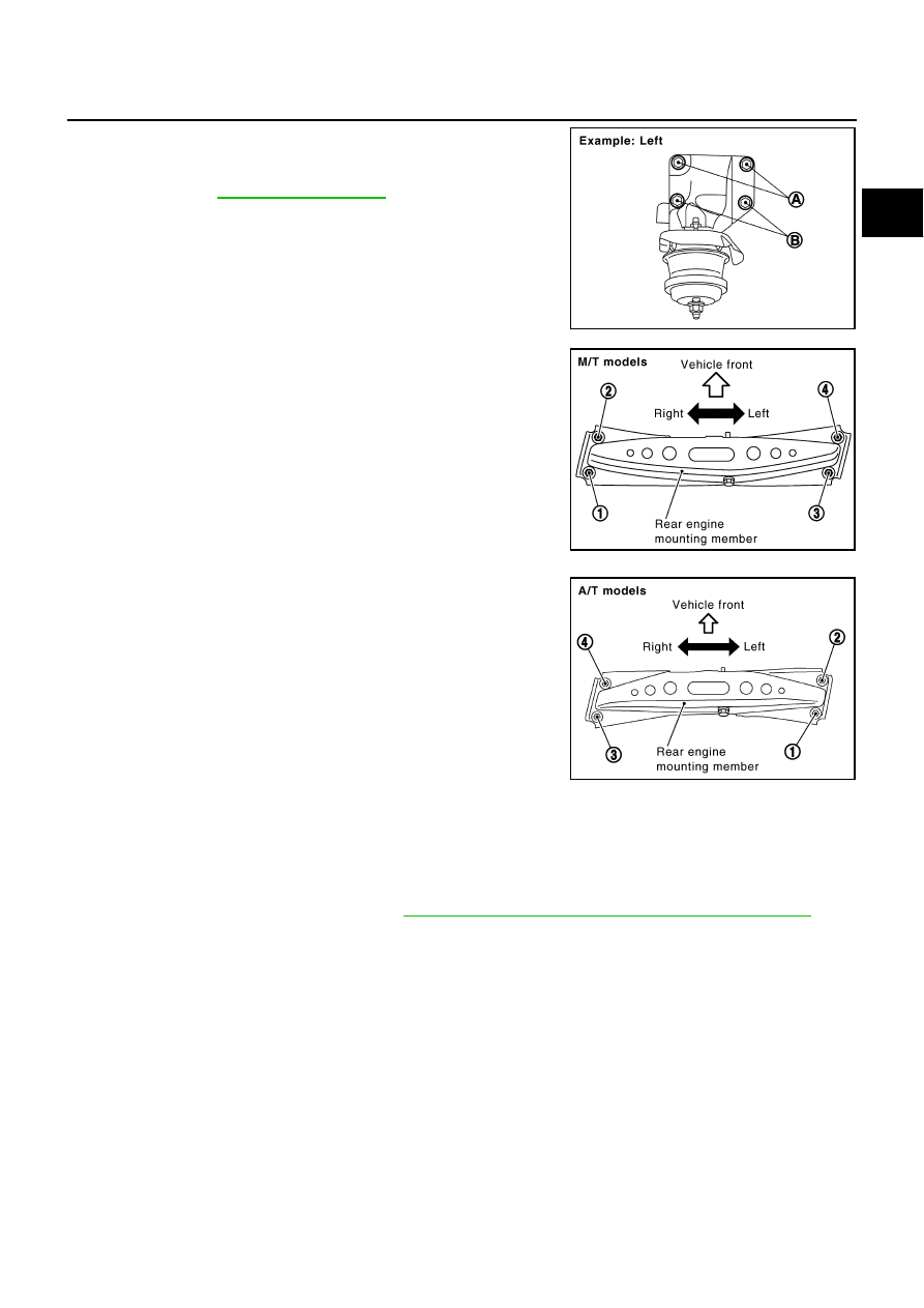
When installing engine mounting brackets (RH and LH) on cylin-
der block, tighten two upper bolts (shown as “A” in the figure)
first. Then tighten two lower bolts (shown as “B” in the figure).

Tighten rear engine mounting member bolts in numerical order
as shown in the figure.

INSPECTION AFTER INSTALLATION
Inspection for Leaks

The following are procedures for checking fluids leak, lubricates leak and exhaust gases leak.

Before starting engine, check oil/fluid levels including engine coolant and engine oil. If less than required
quantity, fill to the specified level. Refer to 

MA-10, "RECOMMENDED FLUIDS AND LUBRICANTS"

 .

Use procedure below to check for fuel leakage.

Turn ignition switch “ON” (with engine stopped). With fuel pressure applied to fuel piping, check for fuel
leakage at connection points.

Start engine. With engine speed increased, check again for fuel leakage at connection points.

Run engine to check for unusual noise and vibration.

Warm up engine thoroughly to make sure there is no leakage of fuel, exhaust gases, or any oil/fluids
including engine oil and engine coolant.

Bleed air from lines and hoses of applicable lines, such as in cooling system.

After cooling down engine, again check oil/fluid levels including engine oil and engine coolant. Refill to the
specified level, if necessary.

PBIC2062E

PBIC1684E

PBIC1683E

EM-136

ENGINE ASSEMBLY

Summary of the inspection items:

* Transmission/transaxle/CVT fluid. power steering fluid, brake fluid, etc.

Items

Before starting engine

Engine running

After engine stopped

Engine coolant

Level

Leakage

Level

Engine oil

Level

Leakage

Level

Other oils and fluid*

Level

Leakage

Level

Fuel

Leakage

Leakage

Leakage

Exhaust gases

Leakage

CYLINDER BLOCK

EM-137

C

D

E

F

G

H

I

J

K

L

M

A

EM

CYLINDER BLOCK

PFP:11010

Components

NBS002V5

PBIC3496E

EM-138

CYLINDER BLOCK

Disassembly and Assembly

NBS002V6

DISASSEMBLY

1.

Remove engine assembly from vehicle, and separate suspension member and transmission from engine.
Refer to 

EM-131, "ENGINE ASSEMBLY"

 .

2.

Remove engine mounting brackets. Refer to 

EM-131, "ENGINE ASSEMBLY"

 .

3.

Remove exhaust manifold (right bank). Refer to 

EM-25, "EXHAUST MANIFOLD AND THREE WAY CAT-

ALYST"

 .

1.

Reinforcement plate

2.

Drive plate (A/T models)

3.

Cover

4.

Gasket

5.

Knock sensor

6.

Cylinder block

7.

Rear oil seal retainer

8.

Oil jet

9.

Thrust bearing

10. Pilot converter (A/T models)

11. Pilot bushing (M/T models)

12. Main bearing

13. Crankshaft

14. Crankshaft key

15. Main bearing cap

16. Main bearing cap bolt

17. Main bearing beam

18. Baffle plate

19. Connecting rod bolt (A/T models)

20. Connecting rod bolt (M/T models)

21. Connecting rod bearing cap

22. Connecting rod bearing

23. Connecting rod

24. Snap ring

25. Piston pin

26. Piston

27. Oil ring

28. Second ring

29. Top ring

30. Flywheel (M/T models)

1.

Cylinder block

2.

Gasket

3.

Water connector

4.

Gasket

5.

Cylinder block heater

6.

Connector protector cap

PBIC2614E


Content   ..  493  494  495  496   ..