Infiniti G35 (V35). Manual - part 490
 

  Index      Infiniti     Infiniti G35 (V35) Coupe - service repair manual 2007 year


Search            


Content   ..  488  489  490  491   ..


Infiniti G35 (V35). Manual - part 490


CAMSHAFT

EM-115

C

D

E

F

G

H

I

J

K

L

M

A

EM

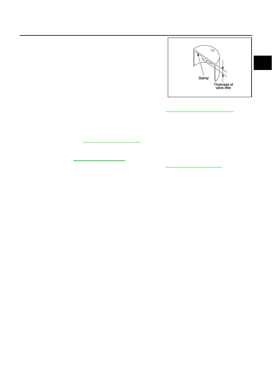
Thickness of new valve lifter can be identified by stamp marks
on the reverse side (inside the cylinder). 
Stamp mark 788U or 788R indicates 7.88 mm (0.3102 in) in
thickness.
NOTE:
Two types of stamp marks are used for parallel setting and for
manufacturer identification.

Available thickness of valve lifter: 27 sizes with range 7.88 to 8.40 mm (0.3102 to 0.3307 in) in steps of
0.02 mm (0.0008 in) (when manufactured at factory). Refer to 

EM-170, "Available Valve Lifter"

 .

CAUTION:

Install identification letter at the end, “U” and “R”, at each of proper positions. (Be careful of
misinstallation between intake and exhaust)

6.

Install selected valve lifter.

7.

Install camshaft. Refer to 

EM-105, "INSTALLATION"

 .

8.

Manually turn crankshaft pulley a few turns. 

9.

Make sure that the valve clearances for cold engine are within the specifications by referring to the speci-
fied values. Refer to 

EM-111, "INSPECTION"

 .

10. Install all removal parts in the reverse order of removal. Refer to 

EM-105, "INSTALLATION"

 .

11. Warm up the engine, and check for unusual noise and vibration.

KBIA0119E

EM-116

OIL SEAL

OIL SEAL

PFP:00100

Removal and Installation of Valve Oil Seal

NBS002UU

REMOVAL

1.

Remove camshaft relating to valve oil seal to be removed. Refer to 

EM-100, "CAMSHAFT"

 .

2.

Remove valve lifters. Refer to 

EM-100, "CAMSHAFT"

 .

3.

Turn crankshaft until the cylinder requiring new oil seals is at TDC. This will prevent valve from dropping
into cylinder.

4.

Remove valve collet.

Compress valve spring with valve spring compressor, attach-
ment, adapter (SST). Remove valve collet with magnet hand.

CAUTION:

When working, take care not to damage valve lifter holes.

5.

Remove valve spring retainer, valve spring.

6.

Remove valve oil seal using valve oil seal puller (SST).

INSTALLATION

1.

Apply new engine oil on new valve oil seal joint and seal lip.

2.

Using valve oil seal drift (SST), press fit valve seal to height “H”
shown in the figure.

NOTE:
Dimension “H”: Height measured before valve spring seat instal-
lation

3.

Install in the reverse order of removal after this step.

PBIC1803E

PBIC0884E

Intake and exhaust

: 14.3 - 14.9 mm (0.563 - 0.587 in)

PBIC2769E

OIL SEAL

EM-117

C

D

E

F

G

H

I

J

K

L

M

A

EM

Removal and Installation of Front Oil Seal

NBS002UV

REMOVAL

1.

Remove the following parts:

Undercover

Drive belts: Refer to 

EM-14, "DRIVE BELTS"

 .

Radiator cooling fan assembly: Refer to 

CO-21, "COOLING FAN"

 .

Starter motor: Refer to 

SC-10, "STARTING SYSTEM"

 .

Crankshaft pulley: Refer to 

EM-59, "TIMING CHAIN"

 .

2.

Remove front oil seal using suitable tool.

CAUTION:

Be careful not to damage front timing chain case and crank-
shaft.

INSTALLATION

1.

Apply new engine oil to both oil seal lip and dust seal lip of new front oil seal.

2.

Install front oil seal.

Install front oil seal so that each seal lip is oriented as shown
in the figure.

Using suitable drift, press-fit until the height of front oil seal is
level with the mounting surface.

Suitable drift: outer diameter 60 mm (2.36 in), inner diameter
50 mm (1.97 in).

CAUTION:

Be careful not to damage front timing chain case and
crankshaft.

Press-fit straight and avoid causing burrs or tilting oil
seal.

3.

Install in the reverse order of removal after this step.

Removal and Installation of Rear Oil Seal

NBS002UW

REMOVAL

1.

Remove oil pan (upper). Refer to 

EM-29, "OIL PAN AND OIL STRAINER"

 .

2.

Remove transmission assembly. Refer to 

MT-18, "TRANSMISSION ASSEMBLY"

 (M/T models) or 

AT-251,

"TRANSMISSION ASSEMBLY"

 (A/T models).

3.

Remove clutch cover and clutch disk (M/T models). Refer to 

CL-16, "CLUTCH DISC, CLUTCH COVER"

 . 

4.

Remove flywheel (M/T models) or drive plate (A/T models). Refer to 

EM-137, "CYLINDER BLOCK"

 .

SEM829E

SEM715A

SEM829E

EM-118

OIL SEAL

5.

Use seal cutter (SST) to cut away liquid gasket and remove rear
oil seal retainer.

CAUTION:

Be careful not to damage mating surfaces.
NOTE:
Regard both rear oil seal and retainer as an assembly.

INSTALLATION

1.

Remove old liquid gasket on mating surface of cylinder block and oil pan (upper) using scraper.

2.

Apply new engine oil to both oil seal lip and dust seal lip of new rear oil seal retainer.

3.

Apply a continuous bead of liquid gasket with tube presser [SST:
WS39930000 (

)] to rear oil seal retainer as shown in the

figure.
Use Genuine RTV Silicone Sealant or equivalent. Refer to

GI-46, "RECOMMENDED CHEMICAL PRODUCTS AND
SEALANTS"

 .

Assembly should be done within 5 minutes after coating.

4.

Install rear oil seal retainer to cylinder block. Refer to 

EM-137, "CYLINDER BLOCK"

 .

Make sure the garter spring is in position and seal lips not inverted.

5.

Install in the reverse order of removal after this step.

SEM830E

PBIC2661E


Content   ..  488  489  490  491   ..