Infiniti G35 (V35). Manual - part 466


  Index      Infiniti     Infiniti G35 (V35) Coupe - service repair manual 2007 year


Search            


Content   ..  464  465  466  467   ..


Infiniti G35 (V35). Manual - part 466


INTAKE MANIFOLD COLLECTOR

EM-19

C

D

E

F

G

H

I

J

K

L

M

A

EM

1.

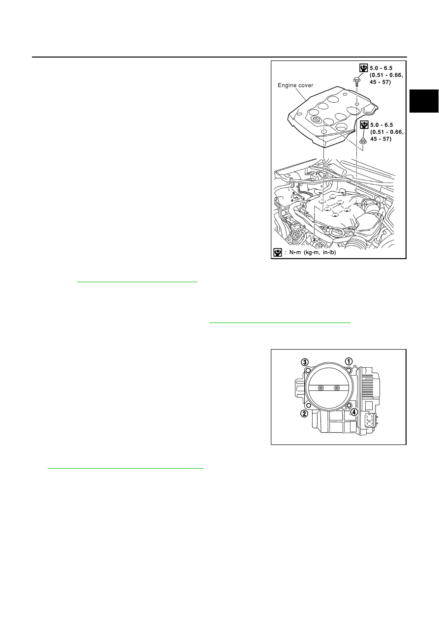
Remove engine cover with power tool.

2.

Drain engine coolant, or when water hose is disconnected, attach plug to prevent engine coolant leakage.
Refer to 

CO-10, "Changing Engine Coolant"

 .

CAUTION:

Perform this step when engine is cold.

Do not spill engine coolant on drive belts.

3.

Remove air cleaner case and air duct. Refer to 

EM-16, "AIR CLEANER AND AIR DUCT"

 .

4.

Remove electric throttle control actuator as follows:

a.

Disconnect harness connector.

b.

Loosen bolts in reverse order as shown in the figure.

CAUTION:

Handle carefully to avoid any shock to electric throttle
control actuator.

Do not disassemble.

5.

Remove fuel sub-tube mounting bolt to disconnect from rear of intake manifold collector (lower). Refer to

EM-38, "FUEL INJECTOR AND FUEL TUBE"

 .

6.

Disconnect vacuum hose and water hose from intake manifold collector (upper).

7.

Remove EVAP canister purge volume control solenoid valve bracket mounting bolt from intake manifold
collector (upper).

KBIA0956E

KBIA0957E

EM-20

INTAKE MANIFOLD COLLECTOR

8.

Loosen bolts in reverse order as shown in the figure to remove
intake manifold collector (upper) with power tool.

9.

Remove PCV hose [between intake manifold collector (lower) and rocker cover (right bank)].

10. Loosen bolts in reverse order as shown in the figure, and

remove the intake manifold collector cover, gasket, intake mani-
fold collector (lower) and gasket with power tool.

INSPECTION AFTER REMOVAL
Surface Distortion

Check the surface distortion of both the intake manifold collector
(upper and lower) mating surfaces with straightedge and feeler
gauge.

If it exceeds the limit, replace intake manifold collector (upper
and/or lower).

PBIC0773E

PBIC0774E

Limit

: 0.1 mm (0.004 in)

PBIC0775E

INTAKE MANIFOLD COLLECTOR

EM-21

C

D

E

F

G

H

I

J

K

L

M

A

EM

INSTALLATION

Note the following, and install in the reverse order of removal.

Indication of Part Installation Direction

Referring to front marks, install parts shown in the figure.

Intake Manifold Collector (Lower)

Tighten in numerical order as shown in the figure.

NOTE:
Tighten mounting bolts to secure gasket (lower), intake manifold col-
lector (lower), gasket (upper), and intake manifold collector cover.

Intake Manifold Collector (Upper)

If stud bolts were removed, install them and tighten to the torque specified below.

Shank length under bolt head varies with bolt location. Install
bolts while referring to numbers shown below and in the figure.
(Bolt length does not include pilot portion.)

Tighten in numerical order as shown in the figure.

Water Hose

Insert hose by 27 to 32 mm (1.06 to 1.26 in) from connector end.

PBIC0776E

PBIC0774E

 : 4.9 - 6.9 N·m (0.5 - 0.7 kg-m, 44 - 61 in-lb)

Bolt

M6 

×

 25 mm (0.98 in)

: 7, 8, 10, 11, 13, 14, 15, 16, 18

M6 

×

 45 mm (1.77 in)

: 2, 4, 5

M6 

×

 60 mm (2.36 in)

: 1, 3, 6, 9

M6 Nut

: 12, 17

PBIC0773E

EM-22

INTAKE MANIFOLD COLLECTOR

Clamp hose at location of 3 to 7 mm (0.12 to 0.28 in) from hose end.

Electric Throttle Control Actuator 

Install gasket with three protrusions for installation check facing any direction other than upward.

Tighten in numerical order as shown in the figure.

Perform the “Throttle Valve Closed Position Learning” when har-
ness connector of electric throttle control actuator is discon-
nected. Refer to 

EC-79, "Throttle Valve Closed Position

Learning"

 .

Perform the “Idle Air Volume Learning” and “Throttle Valve
Closed Position Learning” when electric throttle control actuator
is replaced. Refer to 

EC-79, "Idle Air Volume Learning"

 .

KBIA0957E


Content   ..  464  465  466  467   ..