Infiniti G35 (V35). Manual - part 381
DTC P0442 EVAP CONTROL SYSTEM
EC-405
C
D
E
F
G
H
I
J
K
L
M
A
EC
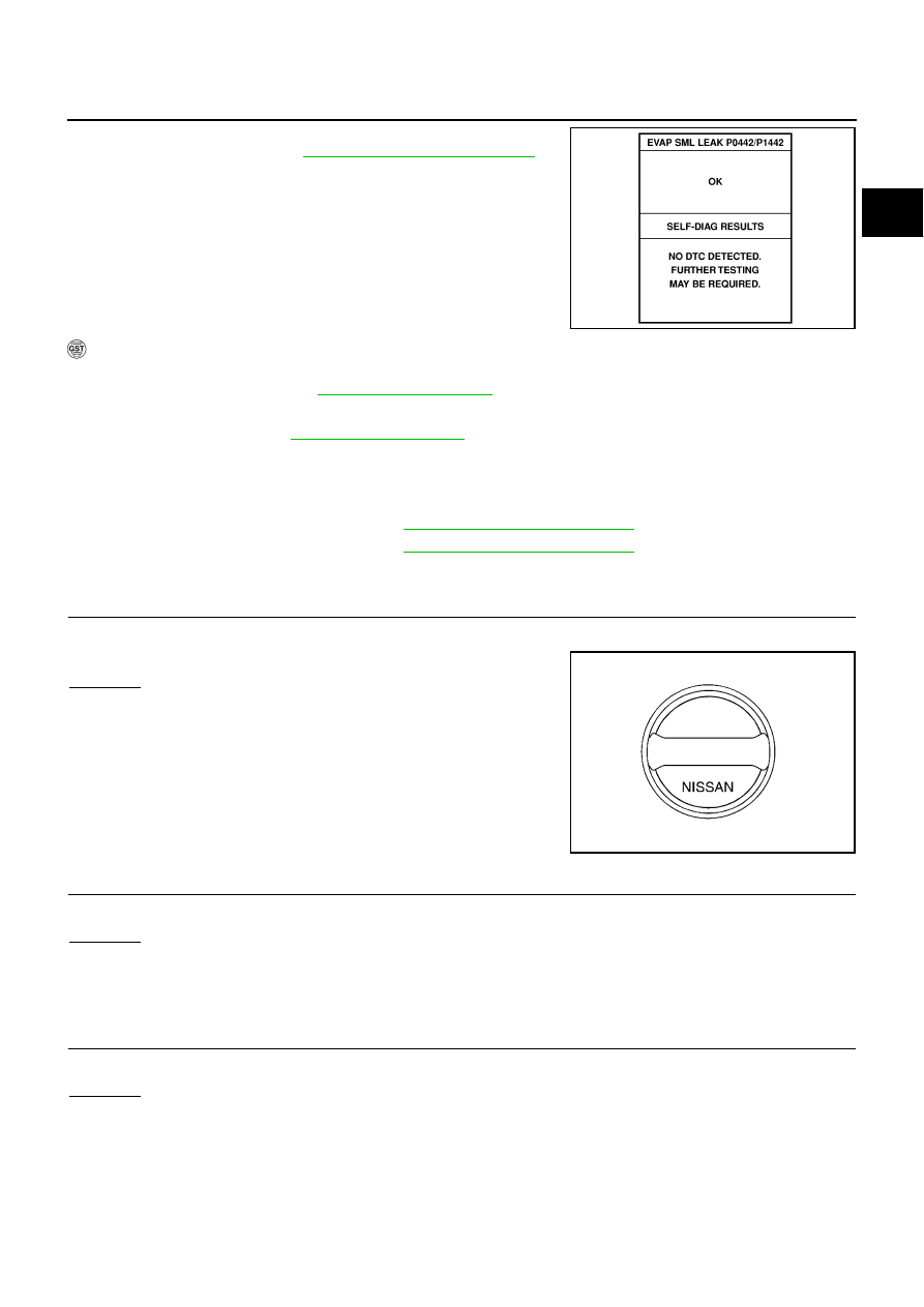
6.
Make sure that “OK” is displayed.
If “NG” is displayed, refer to
EC-405, "Diagnostic Procedure"
.
NOTE:
Make sure that EVAP hoses are connected to EVAP canister
purge volume control solenoid valve properly.
WITH GST
NOTE:
Be sure to read the explanation of
1.
Start engine.
2.
Drive vehicle according to
3.
Stop vehicle.
4.
Turn ignition switch OFF, wait at least 10 seconds and then turn ON.
5.
Select Service $07 with GST.
●
If P0442 is displayed on the screen, go to
EC-405, "Diagnostic Procedure"
.
●
If P0441 is displayed on the screen, go to
EC-400, "Diagnostic Procedure"
.
Diagnostic Procedure
NBS000SS
1.
CHECK FUEL FILLER CAP DESIGN
1.
Turn ignition switch OFF.
2.
Check for genuine NISSAN fuel filler cap design.
OK or NG
OK
>> GO TO 2.
NG
>> Replace with genuine NISSAN fuel filler cap.
2.
CHECK FUEL FILLER CAP INSTALLATION
Check that the cap is tightened properly by rotating the cap clockwise.
OK or NG
OK
>> GO TO 3.
NG
>> 1. Open fuel filler cap, then clean cap and fuel filler neck threads using air blower.
2. Retighten until ratcheting sound is heard.
3.
CHECK FUEL FILLER CAP FUNCTION
Check for air releasing sound while opening the fuel filler cap.
OK or NG
OK
>> GO TO 5.
NG
>> GO TO 4.
SEC763C
SEF915U