Infiniti G35 (V35). Manual - part 322


  Index      Infiniti     Infiniti G35 (V35) Coupe - service repair manual 2007 year


Search            


Content   ..  320  321  322  323   ..


Infiniti G35 (V35). Manual - part 322


DTC P0011, P0021 IVT CONTROL

EC-169

C

D

E

F

G

H

I

J

K

L

M

A

EC

5. 

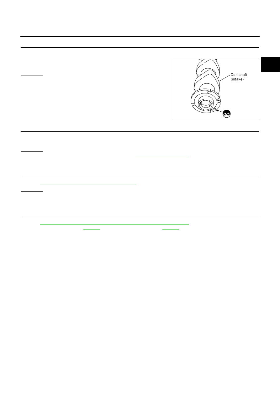
CHECK CAMSHAFT (INT)

Check the following.

Accumulation of debris to the signal plate of camshaft rear end

Chipping signal plate of camshaft rear end

OK or NG

OK

>> GO TO 6.

NG

>> Remove debris and clean the signal plate of camshaft

rear end or replace camshaft.

6. 

CHECK TIMING CHAIN INSTALLATION

Check service records for any recent repairs that may cause timing chain misaligned.
Are there any service records that may cause timing chain misaligned?

Yes or No

Yes

>> Check timing chain installation. Refer to 

EM-59, "TIMING CHAIN"

 .

No

>> GO TO 7.

7. 

CHECK LUBRICATION CIRCUIT

Refer to 

EM-102, "INSPECTION AFTER REMOVAL"

 .

OK or NG

OK

>> GO TO 8.

NG

>> Clean lubrication line.

8. 

CHECK INTERMITTENT INCIDENT

Refer to 

EC-151, "TROUBLE DIAGNOSIS FOR INTERMITTENT INCIDENT"

 .

For Wiring Diagram, refer to 

EC-377

  for CKP sensor (POS) and 

EC-384

  for CMP sensor (PHASE).

>> INSPECTION END

SEC905C

EC-170

DTC P0011, P0021 IVT CONTROL

Component Inspection

NBS000O7

INTAKE VALVE TIMING CONTROL SOLENOID VALVE

1.

Disconnect intake valve timing control solenoid valve harness connector.

2.

Check resistance between intake valve timing control solenoid
valve as follows.

If NG, replace intake valve timing control solenoid valve.
If OK, go to next step.

3.

Remove intake valve timing control solenoid valve.

4.

Provide 12V DC between intake valve timing control solenoid
valve terminals and then interrupt it. Make sure that the plunger
moves as shown in the figure.

CAUTION:

Do not apply 12V DC continuously for 5 seconds or more.
Doing so may result in damage to the coil in intake valve
timing control solenoid valve.
If NG, replace intake valve timing control solenoid valve.

NOTE:
Always replace O-ring when intake valve timing control
solenoid valve is removed.

Removal and Installation

NBS000O8

INTAKE VALVE TIMING CONTROL SOLENOID VALVE

Refer to 

EM-59, "TIMING CHAIN"

 .

Terminal

Resistance

1 and 2

7.0 - 7.5

 [at 20

°

C (68

°

F)]

1 or 2 and ground

∞Ω

(Continuity should not exist.)

PBIB0193E

PBIB2275E

DTC P0014 P0024 EVT CONTROL

EC-171

C

D

E

F

G

H

I

J

K

L

M

A

EC

DTC P0014 P0024 EVT CONTROL

PFP:23795

Description

NBS000O9

SYSTEM DESCRIPTION

*: This signal is sent to the ECM through CAN Communication line 

This mechanism magnetically controls cam phases continuously with the fixed operating angle of the exhaust
valve.
The ECM receives signals such as crankshaft position, camshaft position, engine speed, and engine coolant
temperature. Then, the ECM sends ON/OFF pulse duty signals to the exhaust valve timing control magnet
retarder depending on driving status. This makes it possible to control the shut/open timing of the exhaust
valve to increase engine torque and output in a range of high engine speed.

CONSULT-II Reference Value in Data Monitor Mode

NBS000OA

Specification data are reference values.

Sensor

Input signal to ECM

ECM function

Actuator

Crankshaft position sensor (POS)

Engine speed and piston position

Exhaust valve 
timing control

Exhaust valve timing con-
trol magnet retarder

Camshaft position sensor (PHASE)

Engine coolant temperature sensor

Engine coolant temperature

Exhaust valve timing control position sensor

Exhaust valve timing signal

Wheel sensor

Vehicle speed*

PBIB2765E

MONITOR ITEM

CONDITION

SPECIFICATION

EXH/V TIM B1
EXH/V TIM B2

Engine: After warming up

Shift lever: Neutral

Air conditioner switch: OFF

No load

Idle

5

°

 - 5

°

CA

Engine speed: Above 1,500 rpm

Approx. 0

°

 - 30

°

CA

EX VTC DTY B1
EX VTC DTY B2

Engine: After warming up

Shift lever: Neutral

Air conditioner switch: OFF

No load

Idle

0% - 2%

Engine speed: Above 1,500 rpm

Approx. 0% - 70%

EC-172

DTC P0014 P0024 EVT CONTROL

On Board Diagnosis Logic

NBS000OB

FAIL-SAFE MODE

When the malfunction is detected, the ECM enters fail-safe mode.

DTC Confirmation Procedure

NBS000OC

CAUTION:

Always drive at a safe speed.
NOTE:

If DTC P0014 or P0024 is displayed with DTC P0078, P0084, P1078 or P1084, first perform trouble
diagnosis for DTC P0078, P0084 or P1078, P1084. Refer to 

EC-199, "DTC P0078 P0084 EVT CON-

TROL MAGNET RETARDER"

  or 

EC-512, "DTC P1078 P1084 EVT CONTROL POSITION SENSOR"

 .

If DTC Confirmation Procedure has been previously conducted, always turn ignition switch OFF and wait
at least 10 seconds before conducting the next test. 

TESTING CONDITION:
Before performing the following procedure, confirm that battery voltage is between 10V and 16V at
idle.

 WITH CONSULT-II

1.

Turn ignition switch ON and select “DATA MONITOR” mode with
CONSULT-II.

2.

Start engine and warm it up to the normal operating tempera-
ture.

3.

Maintain the following conditions for at least 6 consecutive sec-
onds.
Hold the accelerator pedal as steady as possible.

4.

Let engine idle for 10 seconds.

5.

If 1st trip DTC is detected, go to 

EC-168, "Diagnostic Procedure"

 .

If 1st trip DTC is not detected, go to next step.

6.

Maintain the following conditions for at least 20 consecutive seconds.

DTC No.

Trouble diagnosis 

name

Detecting condition

Possible cause

P0014
0014
(Bank 1)

Exhaust valve timing 
control performance

There is a gap between angle of target and 
phase-control angle degree.

Crankshaft position sensor (POS)

Camshaft position sensor (PHASE)

Exhaust valve timing control position sensor

Exhaust valve control magnet retarder

Accumulation of debris to the signal pick-up 
portion of the camshaft

Timing chain installation

Exhaust valve timing control pulley assembly

P0024
0024
(Bank 2)

Detected items

Engine operating condition in fail-safe mode

Exhaust valve timing control

The signal is not energized to the exhaust valve timing control magnet retarder and the mag-
net retarder control does not function.

VHCL SPEED SE

100 - 120 km/h (63 - 75 MPH)

ENG SPEED

1,200 - 2,000 rpm (A constant rotation is maintained.)

COOLAN TEMP/S

More than 60

°

C (140

°

F)

B/FUEL SCHDL

More than 7.26 msec

Shift lever

5th position

ENG SPEED

2,000 - 2,950 rpm (A constant rotation is maintained.)

COOLAN TEMP/S

70 - 105

°

C (158 - 221

°

F)

PBIB0164E


Content   ..  320  321  322  323   ..