Infiniti G35 (V35). Manual - part 258


  Index      Infiniti     Infiniti G35 (V35) Coupe - service repair manual 2007 year


Search            


Content   ..  256  257  258  259   ..


Infiniti G35 (V35). Manual - part 258


ENGINE COOLANT

CO-11

C

D

E

F

G

H

I

J

K

L

M

A

CO

3.

Remove reservoir tank, drain engine coolant and clean tank before installing.

4.

Check drained engine coolant for contaminants such as rust, corrosion or discoloration.
If contaminated, flush the engine cooling system. Refer to 

CO-12, "FLUSHING COOLING SYSTEM"

 .

REFILLING ENGINE COOLANT

1.

Install reservoir tank if remove, and radiator drain plug.

CAUTION:

Be sure to clean drain plug and install with new O-ring.

If cylinder block drain plugs are removed, close and tighten them. Refer to 

EM-143, "ASSEMBLY"

 .

2.

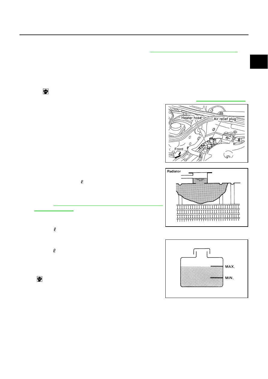
Remove air relief plug on heater hose.

3.

Fill radiator and reservoir tank to specified level.

Pour engine coolant through engine coolant filler neck
slowly of less than 2  (2-1/8 US qt, 1-3/4 lmp qt) a minute
to allow air in system to escape.

Use Genuine NISSAN Long Life Antifreeze/Coolant or
equivalent mixed with water (distilled or demineralized).
Refer to 

GI-46, "RECOMMENDED CHEMICAL PRODUCTS

AND SEALANTS"

 .

When engine coolant overflows air relief hole on heater hose,
install air relief plug with new O-ring.

4.

Warm up engine to normal operating temperature with radiator cap installed.

5.

Run engine at 3,000 rpm for 10 seconds and return to idle speed.

Repeat two or three times.

CAUTION:

Watch water temperature gauge so as not to overheat engine.

6.

Stop engine and cool down to less than approximately 50

°

C (122

°

F).

Cool down using a fan to reduce the time.

If necessary, refill radiator up to filler neck with engine coolant.

Radiator drain plug:

 : 1.2 N·m (0.12 kg-m, 11 in-lb)

PBIC0894E

Engine coolant capacity (Approximate)
(with reservoir tank at “MAX” level)

: 8.7   (9-1/4 US qt, 7-5/8 lmp qt)

SMA182B

Reservoir tank capacity (at “MAX” level)

: 0.8   (7/8 US qt, 3/4 lmp qt)

Air relief plug:


 : 1.2 N·m (0.12 kg-m, 11 in-lb)

SMA412B

CO-12

ENGINE COOLANT

7.

Refill reservoir tank to “MAX” level line with engine coolant.

8.

Repeat steps 3 through 6 two or more times with radiator cap installed until engine coolant level no longer
drops. 

9.

Check cooling system for leaks with engine running.

10. Warm up engine, and check for sound of engine coolant flow while running engine from idle up to 3,000

rpm with heater temperature controller set at several position between “COOL” and “WARM”.

Sound may be noticeable at heater unit.

11. Repeat step 10 three times.

12. If sound is heard, bleed air from cooling system by repeating step 3 through 6 until engine coolant level no

longer drops. 

Clean excess engine coolant from engine.

FLUSHING COOLING SYSTEM

1.

Fill radiator with water until water spills from the air relief hole, then close air relief plug. Fill radiator and
reservoir tank with water and reinstall radiator cap.

2.

Run engine and warm it up to normal operating temperature.

3.

Rev engine two or three times under no-load.

4.

Stop engine and wait until it cools down.

5.

Drain water from the system. Refer to 

CO-10, "DRAINING ENGINE COOLANT"

 .

6.

Repeat steps 1 through 5 until clear water begins to drain from radiator.

RADIATOR

CO-13

C

D

E

F

G

H

I

J

K

L

M

A

CO

RADIATOR

PFP:21400

Components

NBS000LN

Refer to 

GI-10, "Components"

  for symbol marks in the figure.

Removal and Installation

NBS000LO

WARNING:

Do not remove radiator cap when engine is hot. Serious burns could occur from high-pressure engine
coolant escaping from radiator. Wrap a thick cloth around the cap. Slowly turn it a quarter of a turn to
release built-up pressure. Carefully remove radiator cap by turning it all the way.  

REMOVAL

1.

Remove engine cover with power tool. Refer to 

EM-18, "INTAKE MANIFOLD COLLECTOR"

 .

2.

Remove undercover with power tool.

3.

Drain engine coolant from radiator. Refer to 

CO-10, "Changing Engine Coolant"

 .

CAUTION:

Perform when the engine is cold.

4.

Disconnect A/T fluid cooler hoses. (A/T models)

1.

Reservoir tank

2.

Cap

3.

Reservoir tank hose

4.

Radiator hose (upper)

5.

Radiator cap

6.

Upper mount bracket

7.

Mounting rubber (upper)

8.

Radiator

9.

Radiator hose (lower)

10. Mounting rubber (lower)

11.

Radiator drain plug

12. O-ring

13. A/T fluid cooler hose

14. Radiator cooling fan assembly

15. Bracket

A.

To water outlet

B.

To water inlet

C.

To A/T fluid cooler tube

D.

Refer to 

CO-21

PBIC4831E

CO-14

RADIATOR

Install blind plug to avoid leakage of A/T fluid.

5.

Remove air duct (inlet) and air cleaner case. Refer to 

EM-16, "AIR CLEANER AND AIR DUCT"

 .

6.

Remove bracket mounting bolt for anchoring A/C piping from vehicle left side, so that A/C piping can be
moved. 

7.

Remove reservoir tank and bracket.

8.

Remove radiator hoses (upper and lower) and reservoir tank hose.

CAUTION:

Be careful not to allow engine coolant to contact drive belts.

9.

Remove radiator cooling fan assembly. Refer to 

CO-21, "COOLING FAN"

 .

10. Rotate two radiator upper mount brackets 90 degrees in the

direction as shown in the figure, and remove them.

11. Remove two A/C condenser mounting bolts located in upper

part of radiator.

12. Remove radiator as follows:

CAUTION:

Do not damage or scratch A/C condenser and radiator core when removing.

a.

With lifting and pulling radiator in a rear direction, disassemble
lower mount from radiator core support center.

CAUTION:

Because A/C condenser is onto the front-lower portion of
radiator, moving to rear direction should be at minimum.

PBIC0839E

PBIC0840E

PBIC1936E


Content   ..  256  257  258  259   ..