Infiniti G35 (V35). Manual - part 233


  Index      Infiniti     Infiniti G35 (V35) Coupe - service repair manual 2007 year


Search            


Content   ..  231  232  233  234   ..


Infiniti G35 (V35). Manual - part 233


REAR DISC BRAKE

BR-27

C

D

E

G

H

I

J

K

L

M

A

B

BR

REAR DISC BRAKE

PFP:44000

On-Vehicle Inspection

NFS000K0

PAD WEAR INSPECTION

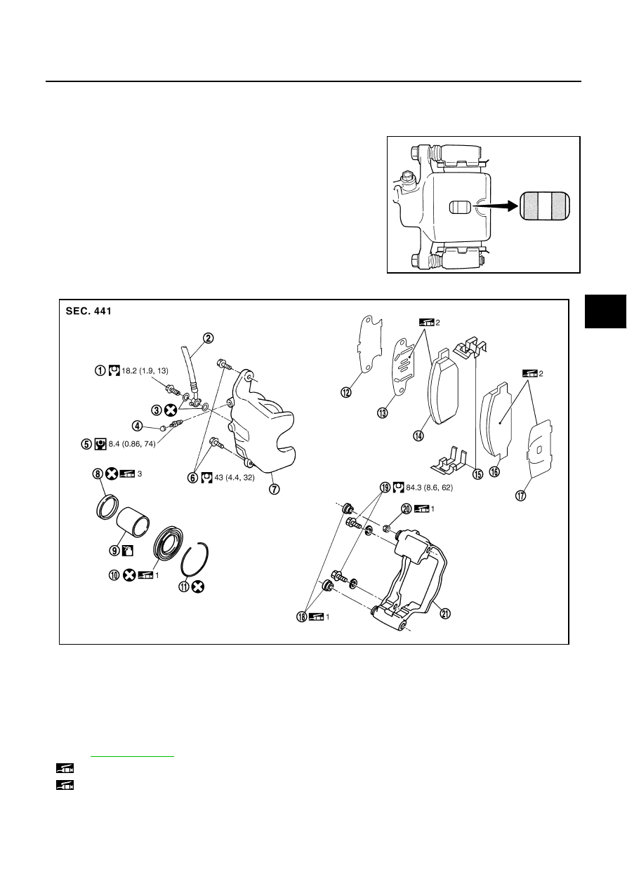
Inspect the thickness from an inspection hole on cylinder body.
Use a scale for inspection if necessary. 

Components

NFS000K1

Standard thickness

: 8.5 mm (0.335 in)

Repair limit thickness

: 2.0 mm (0.079 in) 

BRA0010D

1.

Union bolt

2.

Brake hose

3.

Copper washer

4.

Cap

5.

Bleed valve

6.

Sliding pin bolt

7.

Cylinder body

8.

Piston seal

9.

Piston

10.

Piston boot

11.

Retaining ring

12.

Inner shim cover

13.

Inner shim

14. Inner pad

15.

Pad retainer

16.

Outer pad

17. Outer shim

18.

Slide pin boot

19.

Torque member mounting bolt

20. Bushing

21.

Torque member

Refer to 

GI-10, "Components"

  and the followings for the symbols in the figure.

1: Apply rubber grease.

2: Apply PBC (Poly Butyl Cuprysil) grease or silicone-based grease.

PFIA0686E

BR-28

REAR DISC BRAKE

WARNING:

Clean dust on caliper and brake pad with a vacuum dust collector to minimize the hazard of airborne
particles or other materials.

CAUTION:

While removing cylinder body, never depress the brake pedal because the piston will pop out.

It is not necessary to remove torque member mounting bolts on torque member and brake hose
except for disassembly or replacement of the caliper assembly. In this case, hang cylinder body
with a wire so as not to stretch brake hose.

Do not damage piston boot.

If any shim is subject to serious corrosion, replace it with a new one.

Always replace shims and shim cover as a set when replacing brake pads.

Keep the rotor clean of brake fluid.

Burnish the brake pads and disc rotor mutually contacting surfaces after refinishing or replacing
rotors, after replacing pads, or if a soft pedal occurs at very low mileage. Refer to 

BR-32, "Brake

Burnishing Procedure"

 .

Removal and Installation of Brake Pad

NFS000K2

REMOVAL

1.

Remove tires from vehicle with a power tool.

2.

Remove sliding pin bold (one on top).

3.

Hang cylinder body with a wire, and remove pads, shims, shim cover and pad retainers from torque mem-
ber.

INSTALLATION

1.

Apply PBC (Poly Butyl Cuprysil) grease or silicone-based grease to the rear of the pad and to both sides
of the shim, and install the inner shim and shim cover to the inner pad, and the outer shim to the outer
pad.

2.

Install the pad retainer and pad assemblies to the torque member.

3.

Push the piston in so that the pad is firmly installed, and install cylinder body to torque member.

CAUTION:

When replacing pads with new ones, press in piston until pads can be installed. In this case, care-
fully monitor brake fluid level in reservoir tank because brake fluid will return to master cylinder
reservoir tank.
NOTE:
Use a disc brake piston tool (commercial service tool) to easily press piston.

4.

Install the sliding pin bolt (one on top) and tighten to the specified torque. Refer to 

BR-27, "Components"

 .

5.

Secure disc rotor with wheel nuts. Depress brake pedal a few times until it gets a responsive touch.

6.

Check brake for drag.

7.

Install tires to vehicle.

Removal and Installation of Caliper Assembly

NFS000K3

REMOVAL

1.

Remove tires from vehicle with a power tool.

2.

Fasten disc rotor using wheel nut.

3.

Drain brake fluid. Refer to 

BR-9, "Drain and Refill"

 .

4.

Remove union bolt and then remove brake hose from caliper
assembly.

5.

Remove torque member mounting bolts, and remove caliper
assembly.

CAUTION:

Do not drop brake pad.

6.

Remove disc rotor.

3: Apply polyglycol ether based lubricant.

: Apply brake fluid.

PFIA0292J

REAR DISC BRAKE

BR-29

C

D

E

G

H

I

J

K

L

M

A

B

BR

CAUTION:

Put matching marks on wheel hub assembly and disc rotor, if it necessary to remove disc rotor.

INSTALLATION

CAUTION:

Refill with new brake fluid “DOT 3”.

Never reuse drained brake fluid.

1.

Install disc rotor.

CAUTION:

Matching marks of disc rotor and wheel hub put at the time of removal when reusing disc rotor.

2.

Install caliper assembly to the vehicle, and tighten torque member mounting bolts to the specified torque.
Refer to 

BR-27, "Components"

 .

CAUTION:

Before installing caliper assembly to the vehicle, wipe off oil and grease on washer seats on steer-
ing knuckle and mounting surface of caliper assembly.

3.

Install L shape pin of brake hose to caliper assembly and tighten union bolts to the specified torque. Refer
to 

BR-27, "Components"

 .

CAUTION:

Do not reuse the copper washer for union bolts.

Securely attach brake hose to protrusion on caliper assembly.

4.

Insert new brake fluid and bleed air. Refer to 

BR-10, "Bleeding Brake System"

 .

5.

Check brake for drag.

6.

Install tires to vehicle.

Disassembly and Assembly of Caliper Assembly

NFS000K4

NOTE:
Do not remove torque member, pads, shims, shim cover and pad retainers when disassembling and assem-
bling cylinder body.

DISASSEMBLY

1.

Remove the slide pin bolt, and then remove cylinder body from torque member.

CAUTION:

Do not drop pads, shims, shim cover and pad retainer from torque member.

2.

Remove sliding pin boot from torque member.

3.

As shown in the figure, using a flat-bladed screwdriver, remove
the retaining ring from the cylinder body.

SBR028A

BR-30

REAR DISC BRAKE

4.

Place a wooden block as shown in the figure, and blow air from
union bolt mounting hole to remove pistons and piston boots.

CAUTION:

Do not get fingers caught in the piston.

5.

Using a flat-bladed screwdriver, remove piston seals from cylin-
der body.

CAUTION:

Be careful not to damage cylinder inner wall.

INSPECTION AFTER DISASSEMBLY
Cylinder Body

CAUTION:

Use new brake fluid to clean. Never use mineral oils such as gasoline or kerosene.

Check inner wall of cylinder for corrosion, wear, and damage. If a malfunction is detected, replace cylinder
body.

Minor flaws caused by corrosion or a foreign material can be removed by polishing a surface of inner wall
with a fine sandpaper. Replace the cylinder body, if a malfunction is detected.

Torque Member

Check for wear, cracks, and damage. If a malfunction is detected, replace the affected part.

Piston

CAUTION:

The piston sliding surface is plated. Do not polish with sandpaper.
Check piston surface for corrosion, wear, and damage. If a malfunction is detected, replace applicable part.

Sliding Pin Bolts and Sliding Pin Boots

Check sliding pin bolts and sliding pin boots for wear, damage, and cracks. If a malfunction is detected,
replace applicable part.

ASSEMBLY

1.

Apply polyglycol ether based lubricant to the piston seal, and
install them to the cylinder body.

CAUTION:

Do not reuse piston seal.

BRD0041D

SFIA0999E

SFIA2278E


Content   ..  231  232  233  234   ..