Infiniti G35 (V35). Manual - part 191
INTELLIGENT KEY SYSTEM
BL-151
C
D
E
F
G
H
J
K
L
M
A
B
BL
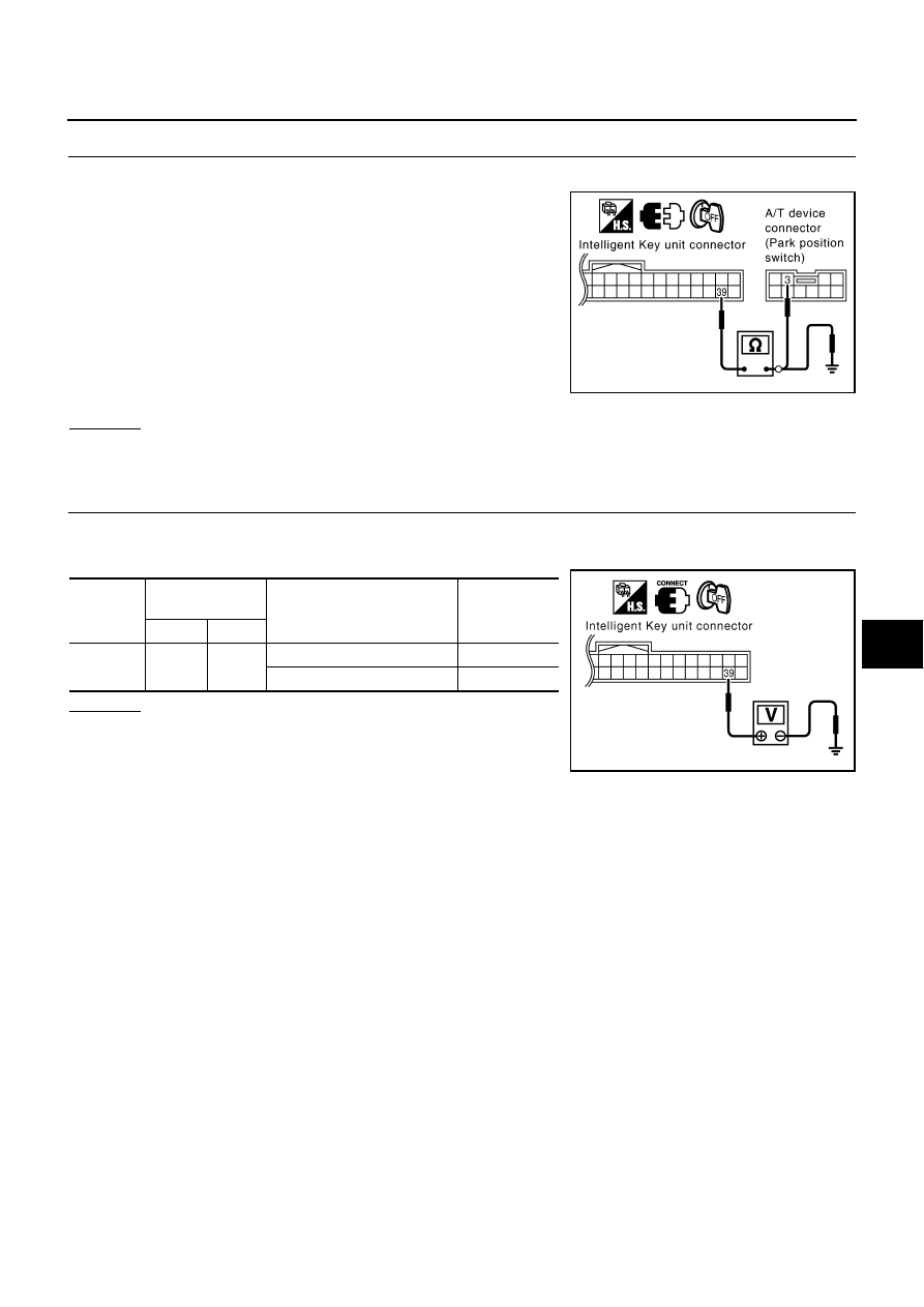
4.
CHECK PARK POSITION SWITCH CIRCUIT
1.
Disconnect Intelligent Key unit connector.
2.
Check continuity between Intelligent Key unit harness connector
M75 terminal 39 and A/T device (park position switch) harness
connector M47 terminal 3.
3.
Check continuity between Intelligent Key unit harness connector
M75 terminals 39 and ground.
OK or NG
OK
>> GO TO 5.
NG
>> Repair or replace harness.
5.
CHECK INTELLIGENT KEY OUTPUT SIGNAL
1.
Connect Intelligent Key unit connector and A/T device (park position switch) connector.
2.
Check voltage between Intelligent Key unit connector and ground.
OK or NG
OK
>> Check condition of harness and connector.
NG
>> Replace Intelligent Key unit.
39 (PU/R) – 3 (PU/R)
: Continuity should exist.
39 (PU/R) – Ground
: Continuity should not exist.
PIIB4349E
Connector
Terminal
(Wire color)
Condition
Voltage (V)
(Approx.)
(+)
(-)
M75
39
(PU/R)
Ground
Selector lever is in “P” position
0
Other than above
Battery voltage
PIIA6805E