Infiniti G35 (V35). Manual - part 137
 

  Index      Infiniti     Infiniti G35 (V35) Coupe - service repair manual 2007 year


Search            


Content   ..  135  136  137  138   ..


Infiniti G35 (V35). Manual - part 137


NAVIGATION SYSTEM

AV-63

C

D

E

F

G

H

I

J

L

M

A

B

AV

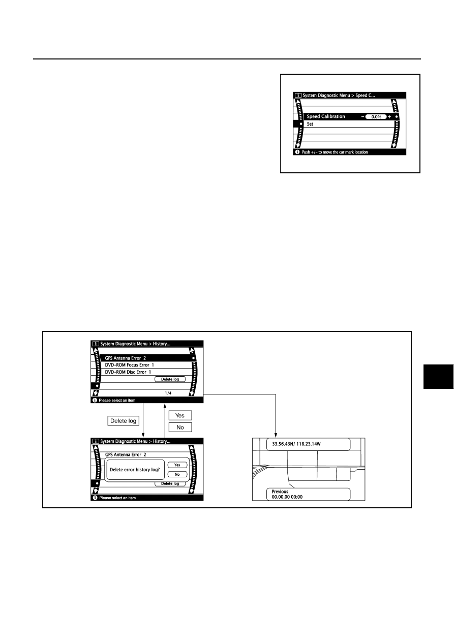
Speed Calibration

Usually the automatic distance correction function adjusts the devia-
tion in distance caused by the tires wearing down or the tire pressure
change. If prompt adjustment is necessary when the tire chains are
installed etc., perform this procedure.

ERROR HISTORY

The diagnostic results of “Self-diagnosis” indicate only malfunction detected during the current  “Self-diagno-
sis”. 
If an error occurred before the ignition switch was turned ON, and does not occur again until “Self-diagnosis” is
completed, the diagnosis result is judged normal. Therefore, errors in the past which cannot be found by “Self-
diagnosis”, must be found by checking the “Error record”.
The error history shows the error occurrence frequency in the past. The frequency of occurrence is displayed
by 2 types: the count down type and the count up type. The type is predetermined according to the error item.
In “Error History”, time and place that the selected error last occurred are displayed. Be careful about the fol-
lowing.

If there is a malfunction with the GPS antenna circuit board in the NAVI control unit, the correct date of
occurrence may not be displayed.

Place of the error occurrence is represented by the position of the current-location mark at the time an
error occurred. If current-location mark has deviated from the correct position, then the place of the error
occurrence cannot be located correctly.

Transition Screen

Count Up Type

At the time the ignition switch is turned ON if the error is detected, the counter increases by 1. If it is nor-
mal when the ignition switch is turned ON, the counter remains the same.

The upper limit of the counter is 50. 51 or more is displayed as 50. It can be reset to 0 by “Delete log”
switch.

SKIB3685E

SKIB7073E

AV-64

NAVIGATION SYSTEM

Error Item

Some error items may be displayed simultaneously according to the cause. If some error items are displayed
simultaneously, the detection of the cause can be performed by analyzing the combination of display items

Error item

Description

Possible cause/Action to take

Switches Connection Error

NAVI switch power supply and ground circuit 
malfunction is detected.

Malfunction is detected on communication 
circuit between NAVI switch and display unit.

Malfunction is detected on communication 
signal between NAVI switch and NAVI control 
unit.

Communication circuit between NAVI 
switch and display unit

NAVI switch power supply and ground cir-
cuit

NAVI switch 

NAVI control unit

Display unit

Front Display Connection Error

Display unit power supply and ground circuit 
malfunction is detected.

Malfunction is detected on communication 
signal between Display unit and NAVI control 
unit.

Display unit power supply and ground

Display unit

NAVI control unit

Front Display Connection Error

Switches Connection Error

Malfunction is detected on communication cir-
cuit between display unit and NAVI control unit.

Communication circuit between display 
unit and NAVI control unit

Display unit

NAVI control unit

IMM Connection Error

Combination meter power supply and ground 
circuit malfunction is detected.

Malfunction is detected on communication 
circuit between NAVI control unit and combi-
nation meter.

Malfunction is detected on communication 
signal between NAVI control unit and combi-
nation meter.

Communication circuit between NAVI con-
trol unit and combination meter

Combination meter power supply and 
ground circuit

Combination meter 

NAVI control unit

GPS Antenna Error

GPS antenna connection malfunction is 
detected.

GPS antenna feeder

GPS antenna

NAVI control unit

FLASH-ROM Error Of Control Unit

NAVI control unit malfunction is detected.

Replace NAVI control unit

Connection Of Gyro

NAVI control unit malfunction is detected.

Replace NAVI control unit

GPS Communication Error

GPS malfunction is detected.

If the symptoms such as the GPS receipt 
malfunction occur, intermittent malfunction 
caused by strong radio interference may be 
detected.
If the malfunction always occurs, replace 
NAVI control unit.

GPS ROM Error

GPS RAM Error

GPS RTC Error

DVDROM Communication Error

Malfunction is detected on DVD-ROM drive 
pickup lens in NAVI control unit.

There is dirt and damage on the map disc.

Map disc

NAVI control unit

DVD-ROM Read Error

DVD-ROM Disc Error

DVD-ROM Mechanism not Detected

DVD-ROM Mechanism Error

DVD-ROM Focus Error

DVD-ROM TOC Error

DVD-ROM Seek Error

DVD-ROM Error Correction Error

DVD-ROM Data Transfer Error

DVD-ROM Data Error

DVD-ROM Time-out

DVD-ROM Loading / Eject Error

NAVIGATION SYSTEM

AV-65

C

D

E

F

G

H

I

J

L

M

A

B

AV

DELETE UNIT CONNECTION LOG

The connection history of unit and error history that is recorded in
NAVI control unit can be cleared, the connection history of the
removed unit can be cleared.

SKIB7074E

AV-66

NAVIGATION SYSTEM

Power Supply and Ground Circuit Inspection for NAVI Control Unit

NKS002G2

1. 

CHECK FUSE

Check the following fuses of the NAVI control unit.

OK or NG

OK

>> GO TO 2.

NG

>> If fuse is blown, be sure to eliminate the cause of malfunction before installing new fuse. Refer to

PG-3, "POWER SUPPLY ROUTING CIRCUIT"

 .

2. 

CHECK POWER SUPPLY CIRCUIT

Check voltage between  NAVI control unit harness connector (A)
M57, (B) M58 and ground.

OK or NG

OK

>> GO TO 3.

NG

>> Check harness for open or short between NAVI control unit and fuse.

3. 

CHECK GROUND CIRCUIT

1.

Turn ignition switch OFF.

2.

Disconnect NAVI control unit connector.

3.

Check continuity between NAVI control unit harness connector
and ground.

OK or NG

OK

>> INSPECTION END

NG

>> Repair harness or connector.

Terminals

Power source

Fuse No.

Connector

Terminal

M57

2

Battery power

37

5

Ignition switch 

ACC or ON

6

M58

63

Ignition switch 

ON or START

12

Terminals

OFF

ACC

ON

(+)

(–)

Connector

Terminal

M57

2

Ground

Battery 
voltage

Battery 
voltage

Battery 
voltage

5

0  V

Battery 
voltage

Battery 
voltage

M58

63

0 V

0 V

Battery 
voltage

SKIB7259E

Terminals

Continuity

Connector

Terminal

Ground

M57

1

Yes

21

SKIB7260E


Content   ..  135  136  137  138   ..