Index Infiniti Infiniti G35 (V35) Coupe - service repair manual 2007 year
Search
Content .. 92 93 94 95 ..
Infiniti G35 (V35). Manual - part 94
TROUBLE DIAGNOSIS
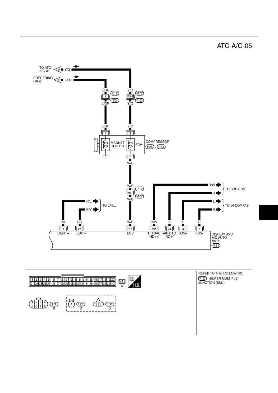
ATC-47
C
D
E
F
G
H
I
K
L
M
A
B
ATC
TJWM0144E