Infiniti G35 (V35). Manual - part 35
DTC P1710 A/T FLUID TEMPERATURE SENSOR CIRCUIT
AT-131
D
E
F
G
H
I
J
K
L
M
A
B
AT
5.
CHECK A/T FLUID TEMPERATURE SENSOR 2
Check A/T fluid temperature sensor 2. Refer to
AT-132, "A/T FLUID TEMPERATURE SENSOR 2"
OK or NG
OK
>> GO TO 6.
NG
>> Replace A/T fluid temperature sensor 2. Refer to
AT-233, "A/T FLUID TEMPERATURE SENSOR
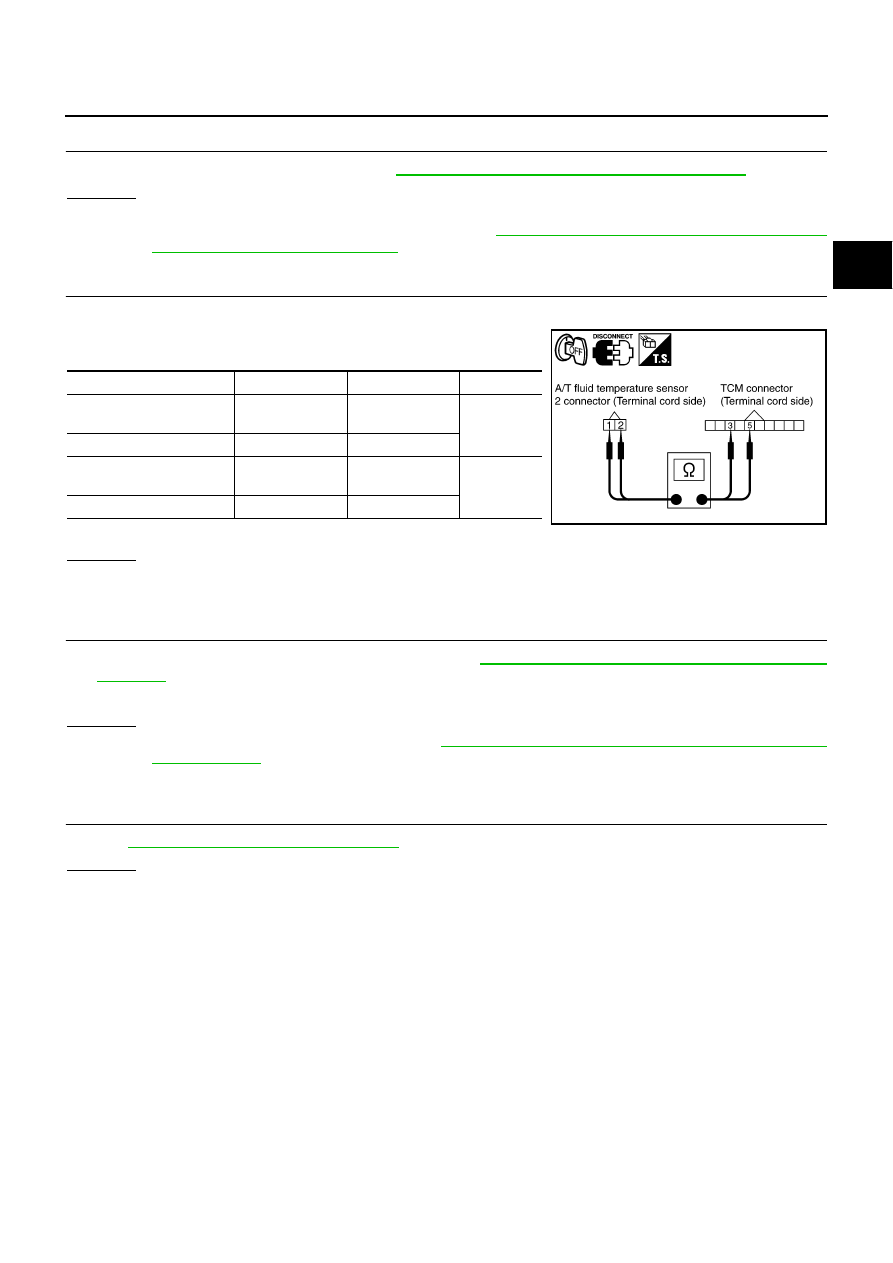
6.
CHECK TERMINAL CORD ASSEMBLY
1.
Disconnect A/T fluid temperature sensor 2 connector and TCM connector.
2.
Check continuity between A/T fluid temperature sensor 2 con-
nector terminals and TCM connector terminals.
3.
If OK, check harness for short to ground and short to power.
OK or NG
OK
>> GO TO 7.
NG
>> Replace open circuit or short to ground and short to power in harness or connectors.
7.
CHECK TCM POWER SUPPLY AND GROUND CIRCUIT
1.
Check TCM power supply and ground circuit. Refer to
AT-172, "MAIN POWER SUPPLY AND GROUND
2.
Reinstall any part removed.
OK or NG
OK
>> Replace control valve with TCM. Refer to
AT-225, "Control Valve with TCM and A/T Fluid Temper-
.
NG
>> Repair or replace damaged parts.
8.
CHECK DTC
Perform
AT-128, "DTC Confirmation Procedure"
.
OK or NG
OK
>> INSPECTION END
NG
>> GO TO 1.
Item
Connector
Terminal
Continuity
A/T fluid temperature sen-
sor 2 connector
F507
1
Yes
TCM connector
F502
3
A/T fluid temperature sen-
sor 2 connector
F507
2
Yes
TCM connector
F502
5
SCIA5462E