Infiniti G35 (V35). Manual - part 15


  Index      Infiniti     Infiniti G35 (V35) Coupe - service repair manual 2007 year


Search            


Content   ..  13  14  15  16   ..


Infiniti G35 (V35). Manual - part 15


TROUBLE DIAGNOSIS

AT-51

D

E

F

G

H

I

J

K

L

M

A

B

AT

5.

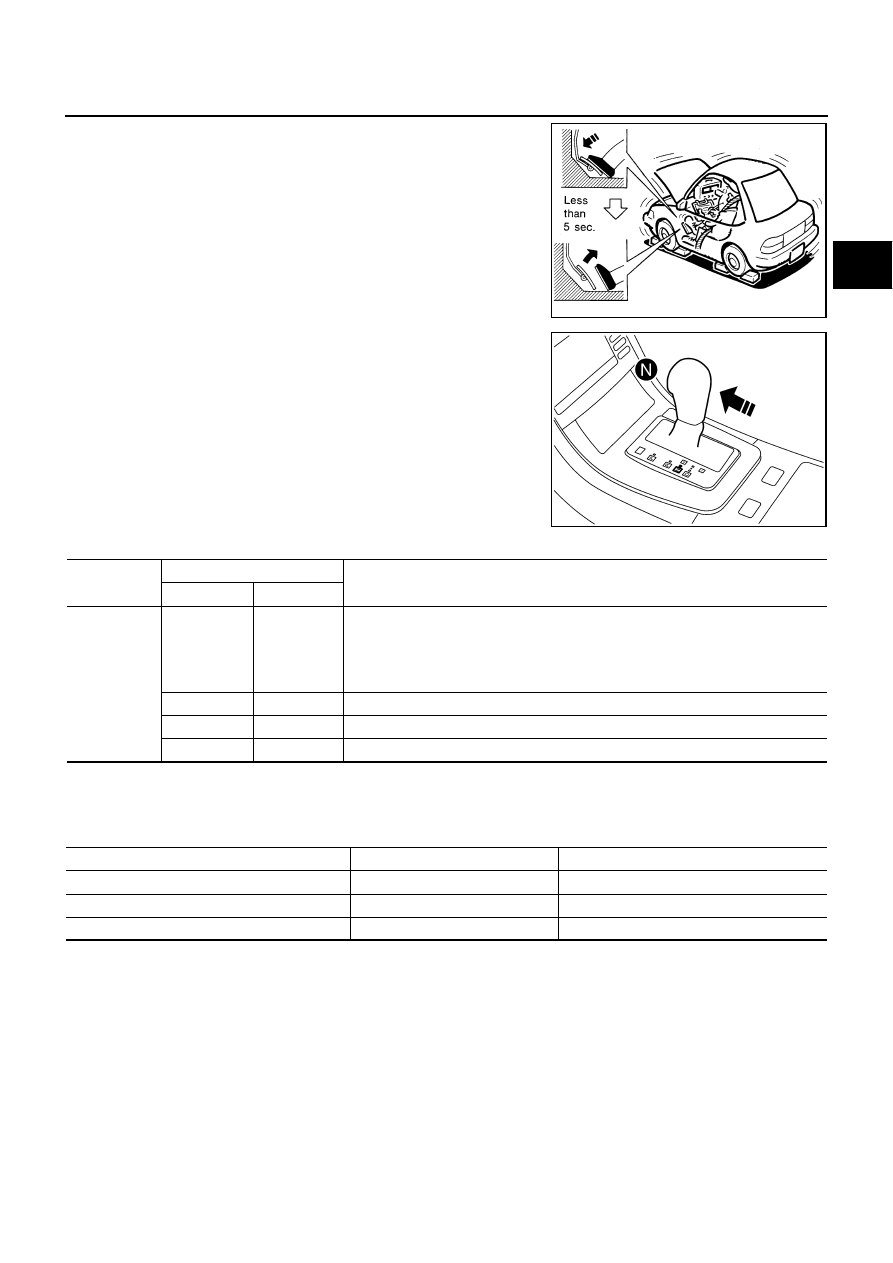
While holding down the foot brake, gradually press down the
accelerator pedal.

6.

Quickly read off the stall speed, then quickly remove your foot
from the accelerator pedal.

CAUTION:

Do not hold down the accelerator pedal for more than 5 sec-
onds during this test.

7.

Move the selector lever to the “N” position.

8.

Cool down the ATF.

CAUTION:

Run the engine at idle for at least one minute.

9.

Repeat steps 5 through 8 with selector lever in “R” position.

Judgment Stall Test

O: Stall speed within standard value position
H: Stall speed higher than standard value
L: Stall speed lower than standard value

Stall test standard value position

Stall speed:

2,650 - 2,950 rpm

SAT514G

SCIA6230E

Selector lever position

Expected problem location

“D”, “M”

“R”

Stall speed

H

O

Forward brake

Forward one-way clutch

1st one-way clutch

3rd one-way clutch

O

H

Reverse brake

L

L

Engine and torque converter one-way clutch

H

H

Line pressure low

Does not shift up “D”, “M” position 1 

 2

Slipping in 2nd, 3rd or 4th gear

Direct clutch slippage

Does not shift up “D”, “M” position 2 

 3

Slipping in 3rd, 4th or 5th gear

high and low reverse clutch slippage

Does not shift up “D”, “M” position 3 

 4

Slipping in 4th or 5th gear

Input clutch slippage

Does not shift up “D”, “M” position 4 

 5

Slipping in 5th gear

Front brake slippage

AT-52

TROUBLE DIAGNOSIS

LINE PRESSURE TEST 
Line Pressure Test Port

Line Pressure Test Procedure

1.

Inspect the amount of engine oil and replenish if necessary.

2.

Drive the car for about 10 minutes to warm it up so that the A/T fluid reaches in range of 50 to 80

°

C (122

to 176

°

F), then inspect the amount of ATF and replenish if necessary.

NOTE:
The A/T fluid temperature rises in range of 50 to 80

°

C (122 to 176

°

F) during 10 minutes of driving.

3.

After warming up remove the oil pressure detection plug and
install the oil pressure gauge [ST2505S001(J-34301-C)].

CAUTION:

When using the oil pressure gauge, be sure to use the O-
ring attached to the oil pressure detection plug.

4.

Securely engage the parking brake so that the tires do not turn.

5.

Start the engine, then measure the line pressure at both idle and
the stall speed.

CAUTION:

Keep the brake pedal pressed all the way down during
measurement.

When measuring the line pressure at the stall speed,
refer to 

AT-50, "STALL TEST"

 . 

6.

After the measurements are complete, install the oil pressure
detection plug and tighten to the specified torque below.

CAUTION:

Do not reuse O-ring.

SCIA2187E

SCIA5309E

SCIA7463E

: 7.3 N·m (0.74 kg-m, 65 in-lb)

SAT493G

TROUBLE DIAGNOSIS

AT-53

D

E

F

G

H

I

J

K

L

M

A

B

AT

Apply ATF to O-ring.

Line Pressure

Judgment of Line Pressure Test

Engine speed

Line pressure

kPa (kg/cm

2

 , psi)

“R” position

“D”, “M” positions

At idle speed

425 - 465 (4.3 - 4.7, 62 - 67)

379 - 428 (3.9 - 4.4, 55 - 62)

At stall speed

1,605 - 1,950 (16.4 - 19.9, 233 - 283)

1,310 - 1,500 (13.4 - 15.3, 190 - 218)

Judgment Possible 

cause

Idle speed

Low for all positions 
(“P”, “R”, “N”, “D”, “M”)

Possible causes include malfunctions in the pressure supply system and low oil pump output.
For example

Oil pump wear

Pressure regulator valve or plug sticking or spring fatigue

Oil strainer 

Þ

 oil pump 

Þ

 pressure regulator valve passage oil leak

Engine idle speed too low

Only low for a specific 
position

Possible causes include an oil pressure leak in a passage or device related to the position after 
the pressure is distributed by the manual valve.

High

Possible causes include a sensor malfunction or malfunction in the line pressure adjustment 
function.
For example

Accelerator pedal position signal malfunction

A/T fluid temperature sensor malfunction

Line pressure solenoid malfunction (sticking in OFF state, filter clog, cut line)

Pressure regulator valve or plug sticking

Stall speed

Line pressure does 
not rise higher than 
the line pressure for 
idle.

Possible causes include a sensor malfunction or malfunction in the pressure adjustment func-
tion.
For example

Accelerator pedal position signal malfunction

TCM breakdown

Line pressure solenoid malfunction (shorting, sticking in ON state)

Pressure regulator valve or plug sticking

Pilot valve sticking or pilot filter clogged

The pressure rises, 
but does not enter the 
standard position.

Possible causes include malfunctions in the pressure supply system and malfunction in the 
pressure adjustment function.
For example

Accelerator pedal position signal malfunction

Line pressure solenoid malfunction (sticking, filter clog)

Pressure regulator valve or plug sticking

Pilot valve sticking or pilot filter clogged

Only low for a specific 
position

Possible causes include an oil pressure leak in a passage or device related to the position after 
the pressure is distributed by the manual valve.

AT-54

TROUBLE DIAGNOSIS

ROAD TEST 
Description

The road test inspects overall performance of the A/T and analyzes possible malfunction causes.

The road test is carried out in the following three stages.

1.

Check before engine is started. Refer to 

AT-54

 . 

2.

Check at idle. Refer to 

AT-54

 .

3.

Cruise test

Inspect all the items from Part 1 to Part 3. Refer to 

AT-56

 , 

AT-58

 , 

AT-59

 . 

Before beginning the road test, check the test procedure and inspection items.

Test all inspection items until the symptom is uncovered. Diagnose NG items when all road tests are com-
plete.

Check Before Engine is Started

NCS000BX

1. 

CHECK A/T CHECK INDICATOR LAMP

1.

Park vehicle on level surface.

2.

Move selector lever to “P” position.

3.

Turn ignition switch OFF and wait at least 10 seconds.

4.

Turn ignition switch ON. (Do not start engine.)

Does A/T CHECK indicator lamp light up for about 2 seconds?

YES

>> 1. Turn ignition switch OFF.

2. Perform self-diagnostics and record all NG items on the 

AT-45, "DIAGNOSTIC WORKSHEET"

. Refer to 

AT-86, "SELF-DIAGNOSTIC RESULT MODE"

 , 

AT-95, "Diagnostic Procedure With-

out CONSULT-II"

 .

3. Go to 

AT-54, "Check at Idle"

 .

NO

>> Stop the road test and go to 

AT-181, "A/T CHECK Indicator Lamp Does Not Come On"

 . 

Check at Idle

NCS000BY

1. 

CHECK STARTING THE ENGINE

1.

Park vehicle on level surface.

2.

Move selector lever to “P” or “N” position.

3.

Turn ignition switch OFF.

4.

Turn ignition switch to “START” position.

Does the engine start?

YES

>> GO TO 2.

NO

>> Stop the road test and go to 

AT-181, "Engine Cannot Be Started in “P” or “N” Position"

 .

2. 

CHECK STARTING THE ENGINE

1.

Turn ignition switch ON. (Do not start engine.)

2.

Move selector lever to “D”, “M” or “R” position.

3.

Turn ignition switch to “START” position.

Does the engine start in either position?

YES

>> Stop the road test and go to 

AT-181, "Engine Cannot Be Started in “P” or “N” Position"

 .

NO

>> GO TO 3.


Content   ..  13  14  15  16   ..