Infiniti FX35 / FX45. Manual - part 692


  Index      Infiniti     Infiniti FX35 / FX45 (S50) - service repair manual 2008 year


Search            


Content   ..  690  691  692  693   ..


Infiniti FX35 / FX45. Manual - part 692


FAX-4

< SERVICE INFORMATION >

[2WD]

FRONT WHEEL HUB AND KNUCKLE

FRONT WHEEL HUB AND KNUCKLE

On-Vehicle Inspection

INFOID:0000000001327506

Make sure the mounting conditions (looseness, back lash) of each component and component status (wear,
damage) are normal.

WHEEL BEARING INSPECTION

• Move wheel hub in the axial direction by hand. Check that there is no looseness of front wheel bearing.

• Rotate wheel hub and make sure there is no unusual noise or other irregular conditions. If there are any

irregular conditions, replace wheel hub and bearing assembly.

Removal and Installation

INFOID:0000000001327507
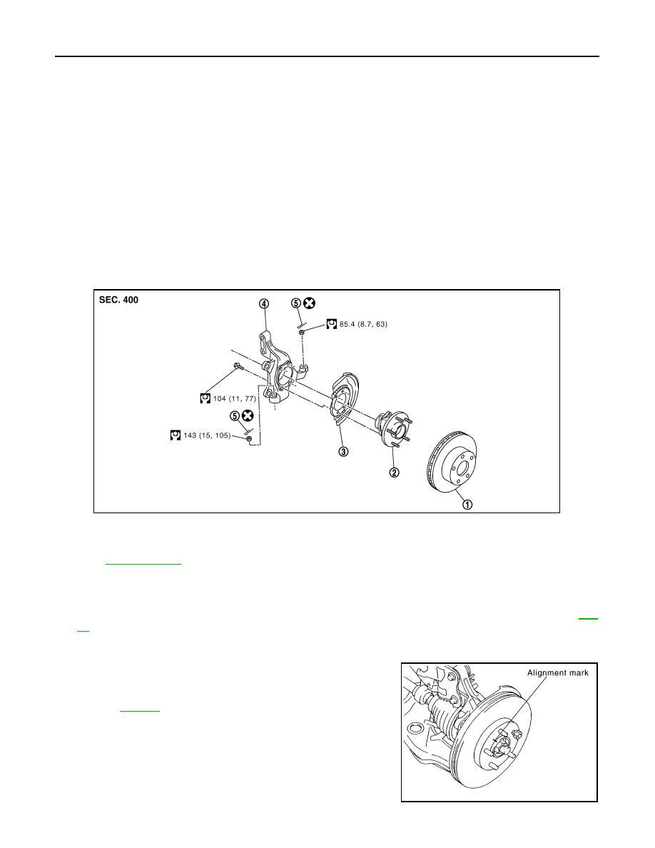
COMPONENTS

REMOVAL

1.

Remove tires from vehicle with power tool.

2.

Remove brake caliper with power tool. Hang it in a place where it will not interfere with work. Refer to 

BR-

18

.

NOTE:
Avoid depressing brake pedal while brake caliper is removed.

3.

Put alignment marks on disc rotor and wheel hub and bearing
assembly, then remove disc rotor.

4.

Remove wheel sensor from wheel hub and bearing assembly.
Refer to 

BRC-52

.

CAUTION:

Do not pull on wheel sensor harness.

5.

Remove cotter pin at steering outer socket, then loosen mount-
ing nut.

Axial end play 

: 0.05 mm (0.002 in) or less

1.

Disc rotor

2.

Wheel hub and bearing assembly

3.

Splash guard

4.

Steering knuckle

5.

Cotter pin

Refer to 

GI-8, "Component"

, for the symbols in the figure.

PDIA1216E

SDIA1480E

FRONT WHEEL HUB AND KNUCKLE

FAX-5

< SERVICE INFORMATION >

[2WD]

C

E

F

G

H

I

J

K

L

M

A

B

FAX

N

O

P

6.

Use a ball joint remover (SST) to remove steering outer socket
from steering knuckle. Be careful not to damage ball joint boot.

CAUTION:

Tighten temporarily mounting nut to prevent damage to
threads and to prevent ball joint remover (SST) from com-
ing off. 

7.

Remove cotter pin at transverse link, then loosen mounting nut.

8.

Use a ball joint remover (SST) to remove transverse link from
steering knuckle. Be careful not to damage ball joint boot.

CAUTION:

Tighten temporarily mounting nut to prevent damage to
threads and to prevent ball joint remover (SST) from com-
ing off.

9.

Remove fixing bolts and nuts between strut assembly and steer-
ing knuckle with power tool.

10. Remove steering knuckle from vehicle.

11. Remove fixing bolts between steering knuckle and wheel hub

and bearing assembly with power tool.

12. Remove splash guard and wheel hub and bearing assembly from steering knuckle.

INSPECTION AFTER REMOVAL

Check for deformity, cracks and damage on each parts, replace if necessary.

Ball Joint Inspection 

• Check for boot breakage, axial looseness, and torque of transverse link and steering outer socket ball joint.

Refer to 

FSU-13

PS-17

.

INSTALLATION

• Refer to "Removal and Installation" for tightening torque. Install in the reverse order of removal.

NOTE:
Refer to component parts location and do not reuse non-reusable parts.

• After removing/installing or replacing axle components, check wheel alignment. Refer to 

FSU-5, "Wheel

Alignment Inspection"

.

• After adjusting wheel alignment, adjust neutral position of steering angle sensor. Refer to 

BRC-8, "Adjust-

ment of Steering Angle Sensor Neutral Position"

.

• Check the following item after service
- Installation condition of wheel sensor harness

SDIA1434E

SDIA1435E

FAX-6

< SERVICE INFORMATION >

[2WD]

SERVICE DATA AND SPECIFICATIONS (SDS)

SERVICE DATA AND SPECIFICATIONS (SDS)

Wheel Bearing

INFOID:0000000001327508

Axial end play

0.05 mm (0.002 in) or less

PRECAUTIONS

FAX-7

< SERVICE INFORMATION >

[AWD]

C

E

F

G

H

I

J

K

L

M

A

B

FAX

N

O

P

SERVICE INFORMATION

PRECAUTIONS

Caution

INFOID:0000000001327509

Observe the following precautions when disassembling and servicing drive shaft.
• Joint sub-assembly does not disassemble because it is non-overhaul parts.
• Perform work in a location which is as dust-free as possible.
• Before disassembling and servicing, clean the outside of parts.
• Prevention of the entry of foreign objects must be taken into account during disassembly of the service loca-

tion.

• Disassembled parts must be carefully reassembled in the correct order. If work is interrupted, a clean cover

must be placed over parts.

• Paper shop cloths must be used. Fabric shop cloths must not be used because of the danger of lint adhering

to parts.

• Disassembled parts (except for rubber parts) should be cleaned with kerosene which shall be removed by

blowing with air or wiping with paper shop cloths.


Content   ..  690  691  692  693   ..