Infiniti FX35 / FX45. Manual - part 460
INDEX FOR DTC
EC-601
< SERVICE INFORMATION >
[VK45DE]
C
D
E
F
G
H
I
J
K
L
M
A
EC
N
P
O
HO2S2 (B1)
P0137
0137
HO2S2 (B1)
P0138
0138
HO2S2 (B1)
P0139
0139
HO2S2 (B2)
P0157
0157
HO2S2 (B2)
P0158
0158
HO2S2 (B2)
P0159
0159
HO2S2 HTR (B1)
P0037
0037
HO2S2 HTR (B1)
P0038
0038
HO2S2 HTR (B2)
P0057
0057
HO2S2 HTR (B2)
P0058
0058
I/C SOLENOID/CIRC
P1752
1752
IAT SEN/CIRCUIT-B1
P0112
0112
IAT SEN/CIRCUIT-B1
P0113
0113
IAT SENSOR-B1
P0127
0127
ICC COMMAND VALUE*
6
P1568
1568
ID DISCORD, IMM-ECM
P1611
1611
IN PULY SPEED
P1715
1715
INT/V TIM CONT-B1
P0011
0011
INT/V TIM CONT-B2
P0021
0021
INT/V TIM V/CIR-B1
P0075
0075
INT/V TIM V/CIR-B2
P0081
0081
INTK TIM S/CIRC-B1
P1140
1140
INTK TIM S/CIRC-B2
P1145
1145
ISC SYSTEM
P0506
0506
ISC SYSTEM
P0507
0507
KNOCK SEN/CIRC-B1
P0327
0327
KNOCK SEN/CIRC-B1
P0328
0328
KNOCK SEN/CIRC-B2
P0332
0332
KNOCK SEN/CIRC-B2
P0333
0333
L/PRESS SOL/CIRC
P0745
0745
LC/B SOLENOID FNCT
P1774
1774
LC/B SOLENOID/CIRC
P1610
1610
LOCK MODE
P1772
1772
MAF SEN/CIRCUIT-B1
P0101
0101
MAF SEN/CIRCUIT-B1
P0102
0102
MAF SEN/CIRCUIT-B1
P0103
0103
MULTI CYL MISFIRE
P0300
0300
NATS MALFUNCTION
P1610 - P1615
1610 - 1615
NO DTC IS DETECTED.
FURTHER TESTING
MAY BE REQUIRED.
P0000
0000
—
P-N POS SW/CIRCUIT
P0850
0850
PNP SW/CIRC
P0705
0705
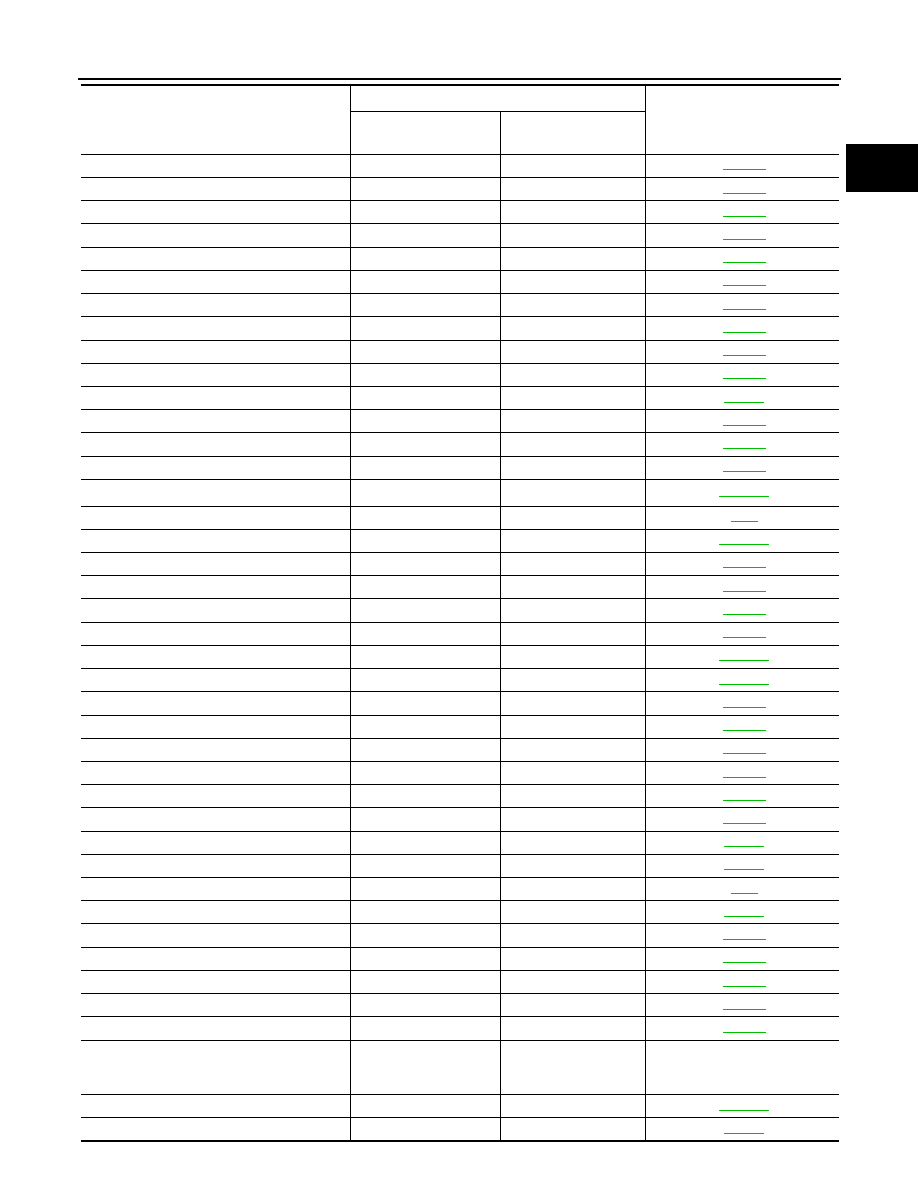
Items
(CONSULT-III screen terms)
DTC*
1
Reference page
CONSULT-III
GST*
2
ECM*
3