Infiniti FX35, FX50 (S51). Manual - part 102
AV
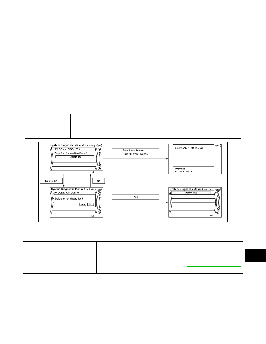
DIAGNOSIS SYSTEM (AV CONTROL UNIT)
AV-181
< SYSTEM DESCRIPTION >
[NAVIGATION (SINGLE MONITOR)]
C
D
E
F
G
H
I
J
K
L
M
B
A
O
P
• If there is a malfunction with the GPS antenna circuit board in the AV control unit, the correct date and time
of occurrence may not be able to be displayed.
• Place of the error occurrence is represented by the position of the current location mark at the time an error
occurred. If current location mark has deviated from the correct position, then the place of the error occur-
rence cannot be located correctly.
• The frequency of occurrence is displayed in a count up manner. The actual count up method differs depend-
ing on the error item.
Count up method A
• The counter resets to 0 if an error occurs when IGN switch is turned ON. The counter increases by 1 if the
condition is normal at a next IGN ON cycle.
• The counter upper limit is 39. Any counts exceeding 39 are ignored.“ The counter can be reset (no error
record display) with the “Delete log” switch or CONSULT-III.
Count up method B
• The counter increases by 1 if an error occurs when IGN switch is ON. The counter will not decrease even if
the condition is normal at the next IGN ON cycle.
• The counter upper limit is 50. Any counts exceeding 50 are ignored. “ The counter can be reset (no error
record display) with the “Delete log” switch or CONSULT-III.
Error item
Some error items may be displayed simultaneously according to the cause. If some error items are displayed
simultaneously, the detection of the cause can be performed by the combination of display items
Display type of occur-
rence frequency
Error history display item
Count up method A
CAN communication line, control unit (CAN), AV communication line, control unit (AV)
Count up method B
Other than the above
JPNIA1788GB
Error item
Description
Possible malfunction factor/Action to take
CAN COMM CIRCUIT
CAN communication malfunction is detect-
ed.
Perform diagnosis with CONSULT-III, and
then repair the malfunctioning parts accord-
ing to the diagnosis results.
Refer to