Hyundai Santa Fe (2006 year). Manual - part 594
FLA -442
FUEL SYSTEM
1. A/C pressure sensor ground
2. A/C pressure sensor signal
3. A/C pressure sensor power
E01
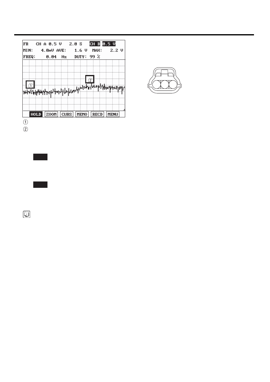
1
2
3
- A/C OFF & Idle
- A/C ON & Idle
SCMF16373L
4)
Is the measured waveform of A/C pressure sensor normal?
YES
▶ Substitute with a known - good PCM and check for proper operation. If the problem is corrected, replace PCM
and go to "Verification of Vehicle Repair" procedure.
NO
▶ Substitute with a known - good A/C pressure sensor and check for proper operation. If the problem is cor-
rected, replace A/C pressure sensor and go to "Verification of Vehicle Repair" procedure.
NOTE
There is a memory reset function on scantool that can erase optional parts automatically detected and memorized
by PCM. After testing PCM on the vehicle, use this function to reuse the PCM on the others
VERIFICATION OF VEHICLE REPAIR
E04CD0ED
Refer to DTC P0532.