Hyundai Santa Fe (2006 year). Manual - part 409
FL -246
FUEL SYSTEM
SPECIFICATION
E2E599C4
Injector Component
Resistance
Injector Operating Voltage
Injector Operating
Current
Injector Control Type
0.330
Ω
(20±1
℃
)
80V
Peak current : 20±1A
Hold in current : 12±1A
Recharging current : 7A
Current control
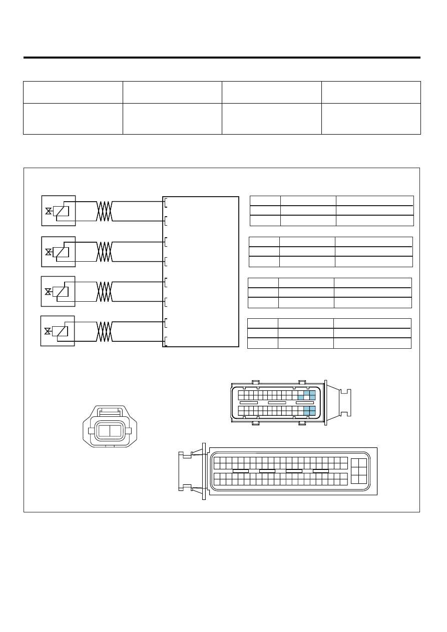
SCHEMATIC DIAGRAM
E4B91D5B
1
1
2
1
2
2
2
1
2
1
ECM C230-A (16)
Injector #1 High side
Injector #1 Low side
ECM C230-A (47)
16 - Injector #1 [High]
33 - Injector #4 [Low]
47 - Injector #1 [Low]
31 - Injector #2 [Low]
46 - Injector #3 [Low]
17 - Injector #4 [High]
1 - Injector #3 [High]
2 - Injector #2 [High]
ECM (C230-A)
Injector #2 (C237-2)
[Injector #1]
1
2
ECM C230-A (2)
Injector #2 High side
Injector #2 Low side
ECM C230-A (31)
[Injector #2]
1
2
ECM C230-A (1)
Injector #3 High side
Injector #3 Low side
ECM C230-A (46)
[Injector #3]
1
2
ECM C230-A (17)
Injector #4 High side
Injector #4 Low side
ECM C230-A (33)
[Injector #4]
Injector #3 (C237-3)
Injector #4 (C237-4)
Injector #1 (C237-1)
C237-1,2,3,4
INJECTOR
#1,#2,#3,#4
C230-K
C230-A
[CIRCUIT DIAGRAM]
[HARNESS CONNECTORS]
[CONNECTION INFORMATION]
Terminal
Connected to
Function
Terminal
Connected to
Function
Terminal
Connected to
Function
Terminal
Connected to
Function
1
2
4
3
6
5
8 7
12
13
16
17
18
23 22
20
21
19
27 26 25 24
28
29
30
14
9
10
11
15
33 32 31
34
37
41
42
40 39 38
35
36
43
44
47 46
49 48
50
53
56
58 57
54
51
52
55
59
60
45
ECM
1
2
1
30 29
31
32
38
39
36
37
35
33
34
40
42 41
46 45 44 43
48 47
50 49
2
3
4
6
5
8
7
12 11 10 9
13
14
15
18 17
19
16
22
25
27 26
23
20
21
24
28
51
75 74
53 52
73
79 78 77 76
80
81
83 82
84
86 85
87
89 88
90
92 91
93
94
57
69 68
70
71
64
54
55
56
61
58
59
60
63 62
65
66
67
72
SCMFL6397L