Hyundai Santa Fe (2006 year). Manual - part 373


  Index      Hyundai     Hyundai Santa Fe - service repair manual 2006 year


Search            


Content   ..  371  372  373  374   ..


Hyundai Santa Fe (2006 year). Manual - part 373


FL -102

FUEL SYSTEM

DTC P0069 BOOST PRESSURE SENSOR CIRCUIT MALFUNCTION
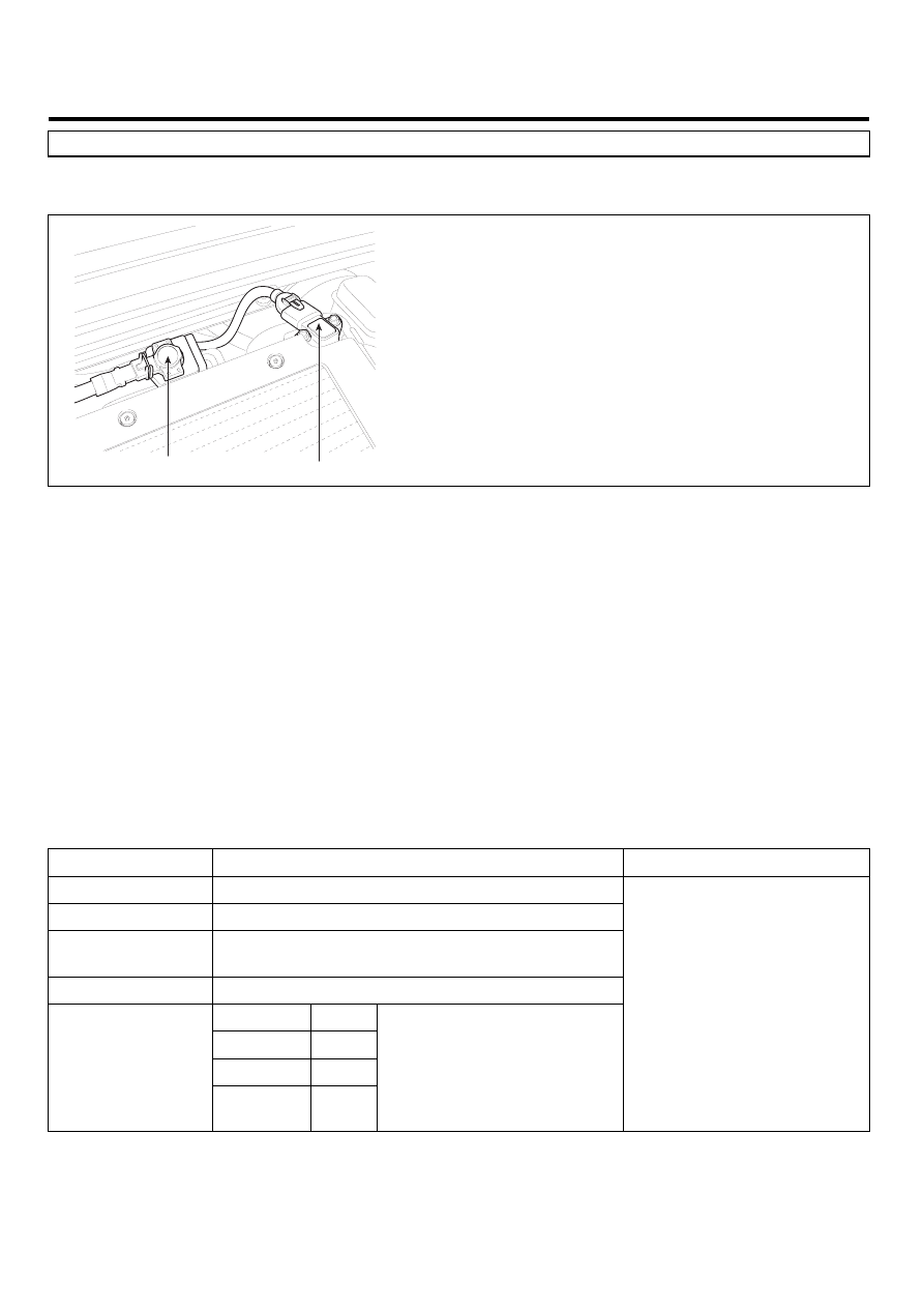
COMPONENT LOCATION

E1BE504F

VGT Control Solenoid Valve

BPS & IATS #2

SCMFL6500L

GENERAL DESCRIPTION

E18B084E

Boost Pressure Sensor(BPS) is installed in intake manifold and senses the pressure of air inside of intake manifold which
is compressed by turbo charager.Measuring mass air flow accurately with the information of intake mainfold pressure,
mass air flow and intake air temperature, ECM performs actuating correction of EGR and VGT.When excessive intake
manifold pressure is detected, engine power generation is limited to protect engine because too highly compressed pres-
sure due to turbo charger may harm engine.

DTC DESCRIPTION

E1A24E17

P0069 is set when the difference between Boost pressure and atmospheric pressure sensor is above 100hpa at below
100RPM(in other word, IG KEY ON condition) for more than 2 sec. This code is due to abnormal output characteristic of
BPS component.

DTC DETECTING CONDITION

EAA4EA2C

Item

Detecting Condition

Possible Cause

DTC Strategy

• Voltage monitoring

Enable Conditions

• IG KEY "ON" (below 100RPM)

Threshold Value

• |Boost pressure - Atmospheric pressure|

is above 100hpa.

Diagnostic Time

• 2 sec.

Fuel cut

NO

EGR Off

YES

Fuel Limit

YES

Fail Safe

Check

Lamp

NO

• Boost pressure is fixed

at 1000 hpa.

• BPS circuit
• BPS component

DTC TROUBLESHOOTING PROCEDURES

FL -103

SPECIFICATION

E96F7817

Pressure [Kpa]

20

100

190

250

Output voltage [V]

0.4±0.077

1.878±0.063

3.541±0.063

4.650±0.077

SCHEMATIC DIAGRAM

E12D020E

BPS & IATS #2

C283

1

2

ECM C230-A (13)

BPS Signal

Reference Voltage (+5V)

ECM C230-A (40)

3

4

ECM C230-A (23)

IATS #2 Signal

Sensor ground

ECM C230-A (53)

ECM (C230-A)

BPS & IATS #2 (C283)

 P

1

2

4

23 - GND

53 - IATS #2 Signal

13 - Reference Voltage (+5V)

40 - BPS Signal

[CIRCUIT DIAGRAM]

[HARNESS CONNECTORS]

[CONNECTION INFORMATION]

Terminal

Connected to

Function

ECM

C230-A

C230-K

1

2

4

3

6

5

8 7

12

13

16

17

18

23 22

20

21

19

27 26 25 24

28

29

30

14

9

10

11

15

33 32 31

34

37

41

42

40 39 38

35

36

43

44

47 46

49 48

50

53

56

58 57

54

51

52

55

59

60
45

1

30 29

31

32

38

39

36

37

35

33

34

40

42 41

46 45 44 43

48 47

50 49

2

3

4

6

5

8

7

12 11 10 9

13

14

15

18 17

19

16

22

25

27 26

23

20

21

24

28

51

75 74
53 52

73

79 78 77 76

80

81

83 82

84

86 85

87

89 88

90

92 91

93

94

57

69 68

70

71

64

54

55

56

61

58

59

60

63 62

65

66

67

72

4

3

2

1

SCMFL6118L

FL -104

FUEL SYSTEM

SIGNAL WAVEFORM AND DATA

E98FDD7C

Fig.1

Fig1). This is the waveform of BPS as accelerating from idle state. Signal voltage rises as accelerating.

              BPS signal

LFIG208A

MONITOR SCANTOOL DATA

E9EBA7FE

1.

Connect Scantool to Data Link Connector (DLC).

2.

Warm engine up to normal operating temperature.

3.

Turn "OFF" electrical devices and A/C.

4.

Monitor "BOOST PRESSURE SENSOR" parameter on the Scantool.

Specification : 1000hpa ± 100hpa(VGT actuator : approx. 76%) at idle

Fig.1

Fig.2

Fig1) Monitor "BOOST PRESSURE SENSOR" parameter on the Scantool at idle after warming engine up. 
         1000hpa 

100hpa(approx. 1 atm) is correct value.

Fig.2) VGT actuator duty and boost pressure atacceleration is shown . If boost pressure rises and reaches certain value, 
          VGT actuator duty stops to drop and keeps steady. Releasing accelerator pedal at this moment, 
          VGT actuator duty drops to approx. 45%,  then if RPM drops to idle range, duty returns to 76%.       

SCMFL6205L

DTC TROUBLESHOOTING PROCEDURES

FL -105

TERMINAL AND CONNECTOR INSPECTION

EE7CA11A

1.

Electrical systems consist of a lot of harness and connectors, poor connection of terminals can cause various prob-
lems and damge of component.

2.

Perform checking procedure as follows.

1)

Check damage of harness and terminals : Check terminals for contact resistance, corrosion and deformation.

2)

Check connecting condition of ECM and component connector : Check terminal seperation, damage of locking
device and connecting condition between terminal and wiring.

NOTE

Disconnect the pin which requires checking at male connector and insert it to the terminal at female connector for
checking connecting condition. ( after checking, reconnect the pin at correct position. )

3.

Is the problem found?

YES

Repair the trouble causing part and go to "Verification of Vehicle Repair".

NO

Go to "Component Inspection ".

COMPONENT INSPECTION

E42A32F0

1.

BPS visual inspection

1)

IG KEY "OFF", ENGINE "OFF".

2)

Disconnect BPS connector.

3)

Check if corrosion and damage in BPS terminal is detected.

4)

Check BPS mounting state, leakage at O’ring, clogged carbon at pressure detecting hall.

5)

Are the problems relevant to BPS found?

YES

Replace BPS if necessary and go to "Verification of Vehicle Repair".

NO

Go to "2. Check BPS output voltage at IG KEY ON" as follows.

2.

Check BPS output voltage at IG KEY ON

1)

IG KEY "OFF", ENGINE "OFF".

2)

Connect Scantool to Data Link Connector (DLC).

3)

IG KEY "ON"

4)

Monitor "ATMOSPHERIC PRESSURE" and "BOOST PRESSURE SENSOR" parameters on scantool.


Content   ..  371  372  373  374   ..