Hyundai: Engine D4FA. Manual - part 168


  Index      Hyundai     Hyundai: Engine D4FA - service repair manual


Search            


Content   ..  166  167  168  169   ..


Hyundai: Engine D4FA. Manual - part 168


FUEL DELIVERY SYSTEM-DIESEL

FLA -543

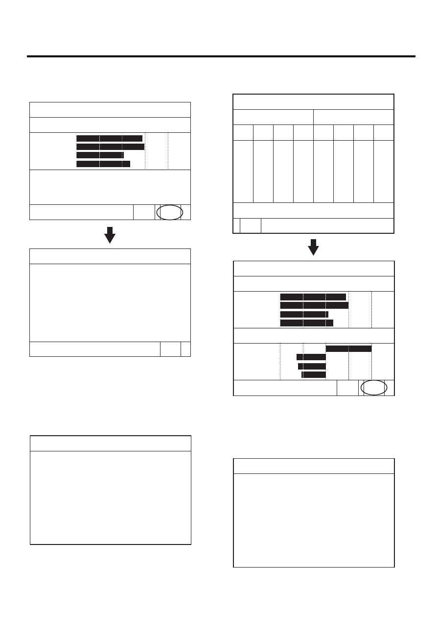
10. Press "AVG" and the data average of each cylinder is

appeared.
Press "HELP" and description of the data is appeared.

Speed(RPM) 650    700      750       800           AVG.

Cylinder engine speed(RPM)       

#1  CYL.

#2  CYL.

#3  CYL.

#4  CYL.

793

800

753

771

PREV

HELP

*The lower engine speed:
 ->The injector injects less quantity 
     than other injectors.
*The higher engine speed:
 ->The injector injects more quantity 
     than other injectors.

7.2  IDLE SPEED COMPARISON

PREV

LFIF660M

11. After pressing "ESC", select "INJECTOR QUANTITY

COMPARISON" and press "[ENTER]".

12. Set the test condition described as below screen and

press "[ENTER]".

7.3  INJECT. QUANTITY COMPARISON

This test is used for detecting
cylinder specific quantity with
individual energizing of injector.
(Cylinder balancing function is
activated.)
* Test condition 
      - Compression test  : Normal
      - Shift lever        : P or N
      - Engine            : Idle
      - Electrical Load : OFF

If you ready, Press [ENTER].

LFIF660O

13. The data od each cylinder about RPM and compen-

sating injection quantity is appeared.

7.3  INJECT. QUANTITY COMPARISON

Analyze the test result.

Eng. Speed(RPM)

#1

#2

#3

#4

#1

#2

#3

#4

792

788

794

792

788

794

790

800

798

802

798

798

802

798

758

760

758

758

758

758

754

774

774

776

774

772

772

770

4.0

4.0

4.0

4.0

4.0

4.0

4.0

-2.9

-2.9

-2.9

-2.8

-2.8

-2.8

-2.9

-2.8

-2.7

-2.7

-2.7

-2.6

-2.8

-2.8

-2.4

-2.4

-2.4

-2.4

-2.4

-2.5

-2.5

ANAL

Speed(RPM) 650    700      750       800           AVG

Cylinder engine speed(RPM)       

<Abnormal state>       

#1  CYL.

#2  CYL.

#3  CYL.

#4  CYL.

791

799

757

773

PREV

HELP

#1  CYL.

#2  CYL.

#3  CYL.

#4  CYL.

  4.0

-2.8

-2.7

-2.3

Injection quantity(mm3)

Quant.(mm ) -4      -2          0          2              AVG

3

LFIF660P

14. Press "HELP" and description of the data is displayed

as below.

7.3  INJECT. QUANTITY COMPARISON

*The positive correction value:
 ->The fuel injection of the cylinder
     is less than that of other cylinder.
*The negative correction value:
 ->The fuel injection of the cylinder
     is more than that of other cylinder.
*Extreme correction value identifies a 
  problematic injector.
After replacinga injector with new one,
reset & confirm the engine condition.

LFIF660R

FLA -544

FUEL SYSTEM

15. Replace the default injector, and then repeat previous

test modes to check if the injector is normal.

COMPONENT INSPECTION

1.

Turn ignition switch "OFF".

2.

Disconnect injector connector.

3.

Measure resistance between the terminals 1 and 2 of
injector connector.

Resistance : 0.22 ~ 0.30Ω (20 ~ 70℃)

LFAC220F

FUEL DELIVERY SYSTEM-DIESEL

FLA -545

COMMON RAIL

DESCRIPTION

ED51BCCF

The common rail stores the fuel at high pressure. At the
same time, the pressure oscillations which are generated
due to the high-pressure pump delivery and the injection
of fuel are damped by the rail volume. This common rail is
common to all cylinders, hence its name ""common rail"".
Even when large quantities of fuel are extracted, the com-
mon rail maintains its inner pressure practically constant.
This ensures that the injection pressure remains constant
from the moment the injector opens.

In order to comply with the wide variety of engine installa-
tion conditions, the common rail with its flow limiters and
the provisions for attaching rail pressure sensor, fuel pres-
sure control valve, and pressure limiter valve is available
in a number of different designs.
The available common rail volume is permanently filled
with pressurized fuel. The compressibility of the fuel re-
sulting from the high pressure is utilized to achieve the ac-
cumulator effect. When fuel leaves the rail for injection, the
pressure in the common rail remains practically constant.
Similarly, the pressure variations resulting from the pulsat-
ing fuel supply from the high-pressure pump are compen-
sated for.

REMOVAL

E0BBB382

CAUTION

• Common

Rail Fuel Injection

System

is

subject to extremely high pressure (Approxi-
mately 1,600 bar)

• Never perform any work on injection system

with engine running or within 30 seconds af-
ter the engine stops.

• Always pay attention to safety precaution.
• Ensure the absolute cleanliness.
• It is not recommended to remove the injectors

without any notice.

1.

urn ignition switch to OFF position.

2.

Disconnect the negative battery (-) terminal and wait
for about 30 seconds.

3.

Remove the high pressure pipe (A) connecting injec-
tors and common rail.

4.

Remove the high pressure pipe (B) connecting high
pressure pump and common rail.

5.

Disconnect the return lines (C).

B

A

C

LGJF502S

6.

Disconnect rail pressure sensor and rail pressure con-
trol valve connectors.

7.

Remove intake manifold. (Refer to "EM" group)

8.

Remove the common rail (E) by unscrewing the two
mounting bolts (F).

E

F

LGJF502T

FLA -546

FUEL SYSTEM

INSTALLATION

EED527BE

1.

Install the common rail(A) with two mounting bolts(B).

Tightening Torque : 14.7 ~ 21.6 N·m (10.9 ~ 15.9 lbf·ft)

A

B

LGJF502U

2.

Install the intake manifold. (Refer to "EM" group).

3.

Connect rail pressure sensor and rail pressure control
valve connectors.

4.

After screwing the high pressure pipe installation nuts
by hand, tighten them at accutate torque using special
service tools(09314-27110, 09314-27130).

SST

LGJF502R

5.

Connect return line(C).

C

AFGF301P

6.

Connect the negative battery(-) terminal.

7.

Start the engine and check for leakage on fuel line.


Content   ..  166  167  168  169   ..