Hyundai: Engine D4FA. Manual - part 127
DIESEL CONTROL SYSTEM
FLA -379
SIGNAL WAVEFORM AND DATA
E2095350
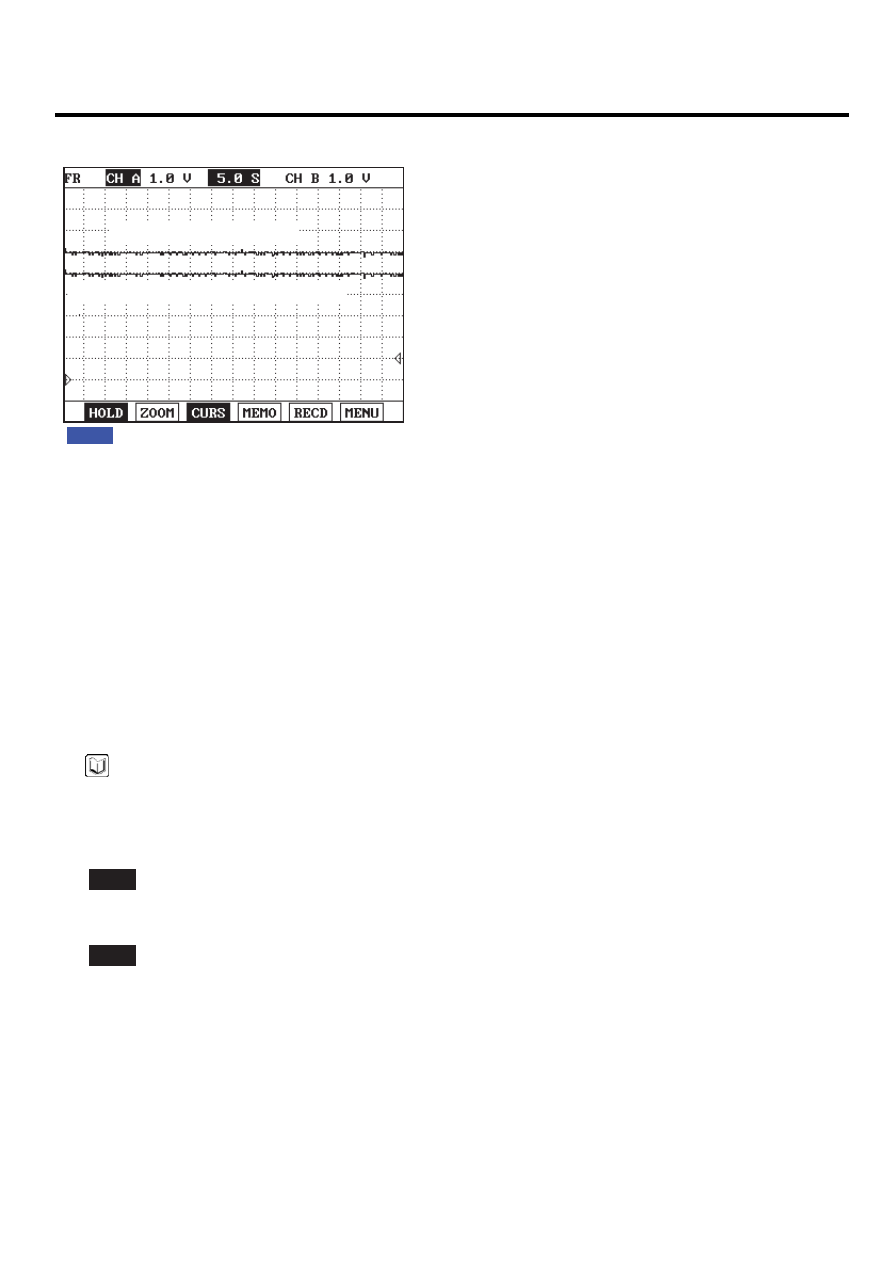
Fig.1
Fig.1) A/C pressure transducer and VSA position Sensor power supply signals are measured simultaneously.
Check if the voltages are within the specification ( 4.8~5.1V) at IG KEY "ON"
Variable swirl control actuator position sensor
Aircon pressure sensor power
EGNG001X
TERMINAL AND CONNECTOR INSPECTION
E1683981
1.
Electrical systems consist of a lot of harness and connectors, poor connection of terminals can cause various prob-
lems and damage of component.
2.
Perform checking procedure as follows.
1)
Check damage of harness and terminals : Check terminals for contact resistance, corrosion and deformation.
2)
Check connecting condition of ECM and component connector : Check terminal seperation, damage of locking
device and connecting condition between terminal and wiring.
NOTE
Disconnect the pin which requires checking at mail connector and insert it to the terminal at female connector for
checking connecting condition. ( after checking, reconnect the pin at correct position )
3.
Is the problem found?
YES
▶ Repair the trouble causing part and go to "Verification of Vehicle Repair".
NO
▶ Go to "Power Circuit Inspection".
POWER CIRCUIT INSPECTION
ED6933C6
1.
Check power circuit voltage
1)
IG KEY "OFF", ENGINE "OFF".
2)
Disconnect A/C pressure transducer connector and variable swirl control actuator connector.
3)
IG KEY "ON".