Hyundai: Engine D4FA. Manual - part 113


  Index      Hyundai     Hyundai: Engine D4FA - service repair manual


Search            


Content   ..  111  112  113  114   ..


Hyundai: Engine D4FA. Manual - part 113


DIESEL CONTROL SYSTEM

FLA -323

DTC DESCRIPTION

E2A1B928

P0611 is set when the problems of more than 2 injector circuits are detected thus, it is difficult to find abnormal injector.
Check "Circuit Inspection" of all injectors

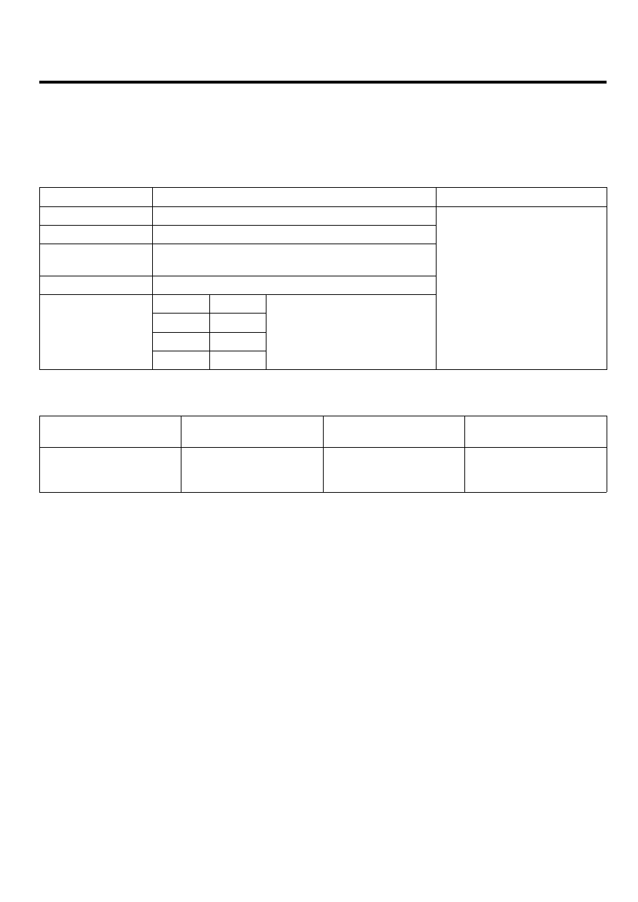
DTC DETECTING CONDITION

EB903688

Item

Detecting Condition

Possible Cause

DTC Strategy

• Current monitoring

Enable Conditions

• IG KEY "ON"

ThresholdValue

• Cylinder recognition is impossible due to the

failure more than 2 injectors.

DiagnosticTime

• Immediately

Fuel Cut

YES

EGR Off

NO

Fuel Limit

NO

Fail Safe

MIL

YES

• Short in Injector circuit
• Injector component

SPECIFICATION

E43C5A79

Injector Component

Resistance

Injector Operating Voltage

Injector Operating

Current

Injector Control Type

0.255Ω ±0.04 (20℃).

80V

Peak current : 18±1A

Hold in current : 12±1A

Recharging current : 7A

Current control

FLA -324

FUEL SYSTEM

SCHEMATIC DIAGRAM

EA35C959

1

1

1

1

1

2

2

2

2

2

C101-1 terminal 16

Injector #1 Low side 

Injector #1 High side

C101-1 terminal 47

16. Injector #1 Low side

33. Injector #4 High side

47. Injector #1 High side

31. Injector #2 High side

46. Injector #3 High side

17. Injector #4 Low side

1. Injector #3 Low side

2. Injector #2 Low side

C101-1 ECM

C113-4 Injector #4

[C113-1 Injector #1]

1

2

C101-1 terminal 2

Injector #2 Low side

Injector #2 High side

C101-1 terminal 31

[C113-2 Injector #2]

1

2

C101-1 terminal 1

Injector #3 Low side

Injector #3 High side

C101-1 terminal 46

[C113-3 Injector #3]

1

2

C101-1 terminal 17

Injector #4 Low side

Injector #4 High side

C101-1 terminal 33

[C113-4 Injector #4]

C113-3 Injector #3

C113-2 njector #2

C113-1 Injector #1

1

2

C113-1 

Injector 

#1

1

2

C113-2 

Injector 

#2

1

2

C113-3 

Injector 

#3

1

2

C113-4 

Injector 

#4

C101-2 ECM

C101-1 ECM

1

30 29

31

32

38

39

36

37

35

33

34

40

42 41

46 45 44 43

48 47

50 49

2

3

4

6

5

8

7

12 11 10 9

13

14

15

18 17

19

16

22

25

27 26

23

20

21

24

28

51

75 74
53 52

73

79 78 77 76

80

81

83 82

84

86 85

87

89 88

90

92 91

93

94

57

69 68

70

71

64

54

55

56

61

58

59

60

63 62

65

66

67

72

[CIRCUIT DIAGRAM]

[HARNESS CONNECTOR]

[CONNECTOR INFORMATION]

Terminal

Terminal

Connected to

Connected to

Function

Terminal

Terminal

Connected to

Connected to

Function

Terminal

Terminal

Connected to

Connected to

Function

Terminal

Terminal

Connected to

Connected to

Function

1

2

4

3

6

5

8 7

12

13

16

17

18

23 22

20

21

19

27 26 25 24

28

29

30

14

9

10

11

15

33 32 31

34

37

41

42

40 39 38

35

36

43

44

47 46

49 48

50

53

56

58 57

54

51

52

55

59

60
45

EGNG008E

DIESEL CONTROL SYSTEM

FLA -325

SIGNAL WAVEFORM AND DATA

EA9DD9FB

Pilot injection1

Pilot injection2

Main injection

Injector current waveform

Fig.1

Fig.2

Fig.3

Fig.4

Fig.1) Injector operating waveform at Low side, It shows 2 pilot and 1 main injection. 
Fig.2) Magnified waveform of main injection at Fig.1)
Fig.3) Injector voltage and current waveforms are measured at the same time using current prove of scope meter.
Fig.4) Magnified waveform of pilot injection at Fig.3)

EGNG008F

TERMINAL AND CONNECTOR INSPECTION

E46C5F40

1.

Electrical systems consist of a lot of harness and connectors, poor connection of terminals can cause various prob-
lems and damge of component.

2.

Perform checking procedure as follows.

1)

Check damage of harness and terminals : Check terminals for contact resistance, corrosion and deformation.

2)

Check connecting condition of ECM and component connector : Check terminal seperation, damage of locking
device and connecting condition between terminal and wiring.

NOTE

Disconnect the pin which requires checking at male connector and insert it to the terminal at female connector for
checking connecting condition. ( after checking, reconnect the pin at correct position. )

3.

Is the problem found?

FLA -326

FUEL SYSTEM

YES

▶ Repair the trouble causing part and go to "Verification of Vehicle Repair".

NO

▶ Go to "Power Circuit Inspection".

POWER CIRCUIT INSPECTION

EC1BE6C5

1.

Check injector connector terminal voltage (failed injector analysis)

1)

IG KEY "OFF", ENGINE "OFF".

2)

Disconnect all injectors.

3)

IG KEY "ON".

4)

Check the voltage of all injector connector terminal 1 and 2.

Specification : Terminal 1 : 0.4V~0.5V
Terminal 2 : 2.0V~2.5V

5)

Is the measured voltage within the specification?

YES

▶ Go to "Component Inspection".

NO

▶ Refer to "DTC" guide corresponding to each problem occurred injector.

Injector #1 related problem :
Refer to P0201for open in injector circuit.
Refer to P0262 for short in injectoer circuit.

Injector #2 related problem :
Refer to P0202 for open in injector circuit.
Refer to P0265 for short in injectoer circuit.

Injector #3 related problem :
Refer to P0203 for open in injector circuit.
Refer to P0268 for short in injectoer circuit.

Injector #4 related problem :
Refer to P0204 for open in injector circuit.
Refer to P0271 for short in injectoer circuit.

COMPONENT INSPECTION

E2473CCF

1.

Check injector component resistance

1)

IG KEY "OFF", ENGINE "OFF".

2)

Disconnect injector connector.


Content   ..  111  112  113  114   ..