Hyundai: Engine D4FA. Manual - part 105
DIESEL CONTROL SYSTEM
FLA -291
SPECIFICATION
E6AAC055
Condition
Brake Pedal Released
Brake Pedal Depressed
Switch 1
Switch 2
Switch 1
Switch 2
switch activated
OFF
ON
ON
OFF
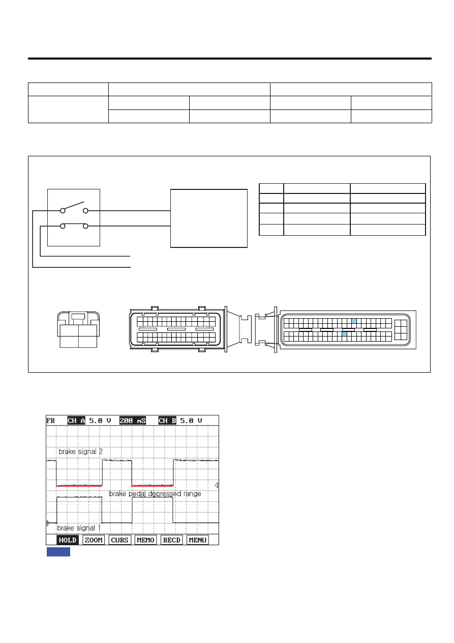
SCHEMATIC DIAGRAM
EE8EC4C4
1
2
3
4
15A STOP LP FUSE
10A SNSR FUSE
Hot at all times
Main relay power
Brake S/W 2 signal
Brake S/W 1 signal
C101-2 terminal 80
C101-2 terminal 38
38. Brake S/W 1 signal
80. Brake S/W 2 signal
C101-2 ECM
E39 Brake S/W
2
4
1
3
Hot at all times (15A STOP LP FUSE)
Main relay power (10A SNSR FUSE)
E39 Brake S/W
1
2
3
4
C101-2 ECM
C101-1 ECM
1
30 29
31
32
38
39
36
37
35
33
34
40
42 41
46 45 44 43
48 47
50 49
2
3
4
6
5
8
7
12 11 10 9
13
14
15
18 17
19
16
22
25
27 26
23
20
21
24
28
51
75 74
53 52
73
79 78 77 76
80
81
83 82
84
86 85
87
89 88
90
92 91
93
94
57
69 68
70
71
64
54
55
56
61
58
59
60
63 62
65
66
67
72
[CIRCUIT DIAGRAM]
[HARNESS CONNECTOR]
[CONNECTOR INFORMATION]
Terminal
Terminal
Connected to
Connected to
Function
1
2
4
3
6
5
8 7
12
13
16
17
18
23 22
20
21
19
27 26 25 24
28
29
30
14
9
10
11
15
33 32 31
34
37
41
42
40 39 38
35
36
43
44
47 46
49 48
50
53
56
58 57
54
51
52
55
59
60
45
EGNG003U
SIGNAL WAVEFORM AND DATA
ECB44D7B
Fig.1) The waveform of brake signal 1 and 2 are measured simultaneously. Both waveforms are symmetrical.
Fig.1
EGNG003V