Hyundai Tiburon (2003 year). Manual - part 88
 

  Index      Hyundai     Hyundai Tiburon - service repair manual 2003 year


Search            


Content   ..  86  87  88  89   ..


Hyundai Tiburon (2003 year). Manual - part 88


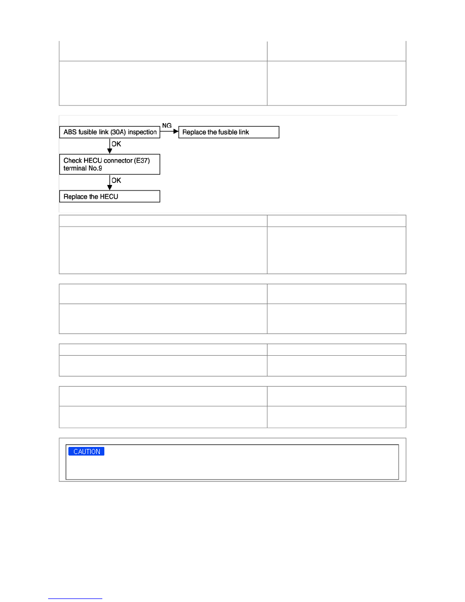
DTC No. C2112 Valve relay 
(Including fuse failure) 

Probable cause 

When the ignition switch is turned ON, the HECU switches the valve relay 
on and off during its initial check. During this time, voltage sent to the 
valve relay is compared to the voltage in the valve power monitor line. If 
no current is detected in the valve power monitor line, the HECU 
determines that there is an open circuit and DTC C2112 is recorded. 

• Faulty wiring harness or connector 

• Faulty HECU 

DTC No. C1605 CAN hardware error 

Probable cause 

Replace the HECU. 

• Interference by means of electronic wave 

• Mismatching of the calculation between main 

and sub processor 

• Defects of the valve coil and valve coil 

operating circuit element 

DTC No. C1611 CAN timeout EMS, C1612 CAN timeout TCU, C1613 
CAN wrong matched transmission
 

Probable cause 

Inspect the EMS or TCU according to the instructions of Engine or T/M 
group. 

• No message from EMS or TCU for 500ms 

• Message from A/T or M/T signal mismatch 

the message from ECM or TCU 

DTC No. C1610 bus off error 

Probable cause 

Check CAN bus wiring. 
Check E37, C33, C133-4 or M42 connectors 

• CAN bus cable open, or short to ground or 

battery 

DTC No. C2402 motor pump failure 
(Motor relay, motor) 

Probable cause 

When the motor power line is normal but no signal is in detected in the 
motor monitor line. 

• Faulty wiring harness 

• Faulty HECU 

Powering the motor with the Hi-Scan (Pro) will discharge the battery. Start and run the engine for a while after testingis 
complete. 


INSPECTION CHART FOR DIAGNOSTIC TROUBLE CODES

DTC 

Trouble Location 

Remarks 

C1101 

Battery voltage over volt 

: 18V or more 

C1102 

Battery voltage low volt 

: 9.5V or less 

C1200 

FL wheel sensor 

: open or short to ground 

C1201 

- Range/Performance 

: speed jump or damaged 
exciter 

C1202 

- No signal 

: air-gap error or wrong excite 

C1203 

FR wheel sensor 

: open or short to ground 

C1204 

- Range/Performance 

: speed jump or damaged 
exciter 

C1205 

- No signal excite 

: air-gap error or wrong excite 

C1206 

RL wheel sensor 

: open or short to ground 

C1207 

- Range/Performance 

: speed jump or damaged 
exciter 

C1208 

- No signal excite 

: air-gap error or wrong excite 

C1209 

RR wheel sensor 

: open or short to ground 

C1210 

- Range/Performance 

: speed jump or damaged 
exciter 

C1211 

- No signal 

: air-gap error or wrong excite 

C1604 

ECU hardware 

: ECU internal or valve failure 

C2112 

Valve relay 

: valve relay or fuse failure 

C2402 

Motor-Electrical 

: open or short to battery, 
motor relay, fuse or motor 
lock fail 

C2227 

Brake disc overheat 

Only TCS 

C1503 

TCS switch failure 

With TCS switch 

C1610 

CAN bus off failure 

Only TCS 

C1611 

EMS time-out failure 

Only TCS 

C1612 

TCU time-out failure 

Only TCS 


C1613 

TCU un-matching failure 

Only TCS 

C1605 

CAN hardware failure 

Only TCS 

FAILSAFE SPECIFICATION

DETECT MODE

THE ABILITY OF DETECTING A FAILURE

THE MANAGEMENT OF FAILURE DETECTION

1. System down. Both the ABS (TCS) and the EBD function are inhibited and the ABS (TCS) and the EBD warning lamps are 

activated. 
If this happens, the valve relay and all solenoids are prevented from being switched on. 

2. Only the ABS (TCS) function is inhibited. The ABS (TCS) warning lamp is activated and the EBD warning lamp is not 

activated. 

3. Sensor failure outside the ABS control cycle. 

(1) Only one sensor fails : take the same action as management 2. 

(2) More than two sensors fail : take the same action as management 1. 

4. Sensor failure inside the ABS control cycle. 

(1) One front sensor fails : inhibit the ABS control of the failed-wheel and maintain ABS control of the normal wheels. 

After the controller completes the ABS control, take the same action as in management 2. 

(2) One rear sensor fails : inhibit ABS control of both front wheels and the pressure of both rear wheels is decreased. 

After the controller completes the ABS control, take the same action as in management 2. 

(3) More than two sensor fail : take the same action as in management 1. 

5. Low operating voltage 

(1) Outside the ABS control cycle : inhibit the ABS (TCS) control of front wheels and allow ABS control of rear wheels, 

deactivating the motor. 
The ABS (TCS) warning lamp is directly switched on. 
When the voltage recovers to the normal operating range, enable the ABS function and the ABS (TCS) warning lamp 
is switched off and erases theerror code of low voltage. 

(2) Inside the ABS control cycle : inhibit the ABS control of the front wheels and allow the the ABS control of rear wheels, 

deactivating the motor. 
The ABS (TCS) warning lamp is directly switched on and remains on. The error code is always stored. 

6. Motor error during the ABS control cycle. Inhibit the ABS control of front wheels, allow ABS control of the rear wheels and 

ABS (TCS) warning lampis switched ON at the end of ABS control. 

7. TCS failure 

Inhibit the TCS control and allow the ABS/EBD control. Meanwhile, stop checking the TCS switch failure under the TCS 
control. 


Content   ..  86  87  88  89   ..