Hummer H3. Manual - part 954
 

  Index      Hummer     Hummer H3 - service repair manual 2006-2009 year


Search            


Content   ..  952  953  954  955   ..


Hummer H3. Manual - part 954


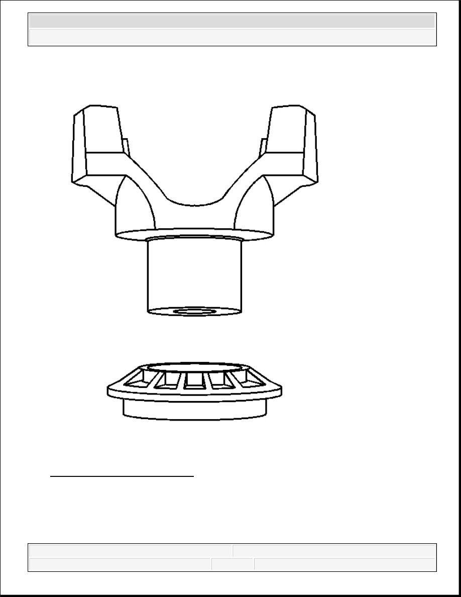
Fig. 50: View Of Dust Deflector 
Courtesy of GENERAL MOTORS CORP. 

1. Install the new deflector onto the pinion yoke, using a soft-faced hammer. 


2007 Hummer H3 

2007 Driveline/Axle Front Drive Axle - H3


Fig. 51: Installing Pinion Oil Seal 
Courtesy of GENERAL MOTORS CORP. 

2. Install the new oil seal by doing the following: 

1. Position the oil seal in the bore.  

2. Install the J 21128 over the oil seal. See Special Tools.  

3. Strike the J 21128 with a hammer, until the seal flange seats on the axle housing 

surface. See Special Tools.  

3. Apply sealant GM P/N 12346004 (Canadian P/N 10953480) or equivalent, to the splines of 

the drive pinion yoke.  

4. Install the pinion yoke. 

Align the reference marks made during removal. 

IMPORTANT: Drive the seal in straight, not at an angle, as this will damage 

the aluminum housing.


2007 Hummer H3 

2007 Driveline/Axle Front Drive Axle - H3


5. Seat the pinion yoke onto the pinion shaft by tapping it with a soft-faced hammer, until a 

few pinion shaft threads show through the yoke.  

6. Install the washer and a new pinion nut. 

Fig. 52: Holding Pinion Yoke With Special Tool 
Courtesy of GENERAL MOTORS CORP. 

7. Install the J 8614-01 (1) onto the pinion yoke, as shown. See Special Tools

NOTE:

Do not hammer the pinion flange/yoke onto the pinion shaft. 
Pinion components may be damaged if the pinion flange/yoke 
is hammered onto the pinion shaft.

NOTE:

Refer to Fastener Notice .


2007 Hummer H3 

2007 Driveline/Axle Front Drive Axle - H3


8. Tighten the pinion nut while holding the J 8614-01 (1). See Special Tools

Tighten: Tighten the pinion nut, until the pinion end play is just taken up. Rotate the pinion 
while tightening the nut to seat the bearings. 

9. Measure the rotating torque of the pinion using an inch-pound torque wrench. 

Compare the measurement of the rotating torque to the measurement recorded earlier. 

Specification: The rotating torque of the pinion nut should be 0.40-0.57 N.m (3-5 lb in) 
greater than the torque recorded during removal. 

10. If the rotating torque is not within specifications, continue to tighten the pinion nut. 

Tighten: Tighten the pinion nut in small increments, as needed, until the torque required in 
order to rotate the pinion is 0.40-0.57 N.m (3-5 lb in) greater than the torque recorded 
during removal. 

11. Once the specified torque is obtained, rotate the pinion several times to ensure the bearings 

have seated. Recheck the rotating torque and adjust, if necessary.  

12. Install the front propeller shaft. Refer to Front Propeller Shaft Replacement .  

13. Install the EPS. Refer to Engine Shield Replacement .  

14. Install the brake calipers. Refer to Front Brake Caliper Replacement .  

15. Fill the drive axle. Refer to Front Axle Lubricant Replacement.  

16. Lower the vehicle.  

DIFFERENTIAL CARRIER ASSEMBLY BUSHING AND BRACKET REPLACEMENT 

IMPORTANT: If the rotating torque is exceeded, the pinion will have to be 

removed and a new collapsible spacer installed.


2007 Hummer H3 

2007 Driveline/Axle Front Drive Axle - H3


Content   ..  952  953  954  955   ..