Hummer H3. Manual - part 612
 

  Index      Hummer     Hummer H3 - service repair manual 2006-2009 year


Search            


Content   ..  610  611  612  613   ..


Hummer H3. Manual - part 612


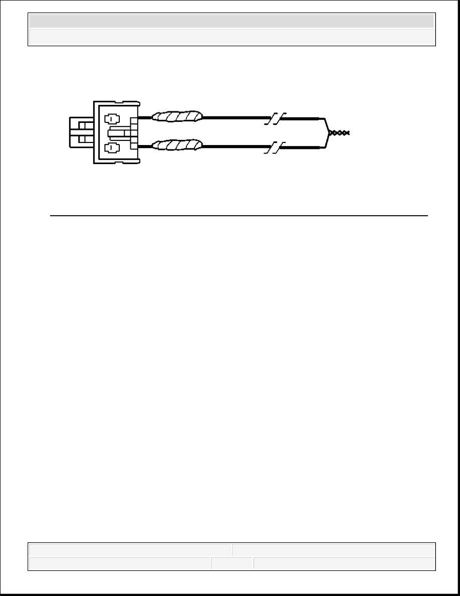
Fig. 104: Taping Remaining Connector Wire Lead To Remaining Deployment Wire 
Courtesy of GENERAL MOTORS CORP. 

59. Twist together, bend and tape the remaining connector wire lead to the remaining 

deployment wire. 


2007 Hummer H3 

2007 RESTRAINTS Supplemental Inflatable Restraints - H3


Fig. 105: Locating Roof Rail Module Connector 
Courtesy of GENERAL MOTORS CORP. 

60. Connect the deployment harness to the roof rail module yellow connector. 


2007 Hummer H3 

2007 RESTRAINTS Supplemental Inflatable Restraints - H3


Fig. 106: Routing The Deployment Harness Out Of The Vehicle's Passenger Side 
Courtesy of GENERAL MOTORS CORP. 

61. Route the deployment harness out of the passenger side of the vehicle.  

62. Completely cover the windshield and the front door window openings with a drop cloth.  

63. Stretch to the full length all of the deployment harness wires on the right side of the vehicle.  

64. Deploy each deployment loop one at a time.  

65. Place a power source, 12 V minimum/2 A minimum, such as a vehicle battery, near the 

shorted end of the harnesses.  

66. Separate one set of wires and touch the wire ends to the power source in order to deploy the 

selected inflator module.  

67. Disconnect the deployment harness from the power source and twist the wire ends together.  

68. Continue the same process with the remaining deployment harnesses. 


2007 Hummer H3 

2007 RESTRAINTS Supplemental Inflatable Restraints - H3


Fig. 107: Routing The Deployment Harness Out Of The Vehicle's Driver Side 
Courtesy of GENERAL MOTORS CORP. 

69. Stretch to the full length all of the deployment harness wires on the left side of the vehicle.  

70. Deploy each deployment loop one at a time.  

71. Place a power source, 12 V minimum/2 A minimum, such as a vehicle battery, near the 

shorted end of the harnesses.  

72. Separate one set of wires and touch the wires ends to the power source in order to deploy 

the selected inflator modules.  

73. Disconnect the deployment harness from the power source and twist the wire ends together.  

74. Continue the same process with the remaining deployment harnesses.  

75. Remove the drop cloth from the vehicle.  

76. Disconnect all harnesses from the vehicle.  

77. Discard the harnesses.  

78. Scrap the vehicle in the same manner as a non-SIR equipped vehicle.  

79. If one or all of the inflator modules did not deploy, perform the following steps to remove 

the undeployed modules from the vehicle: 


Inflatable Restraint Steering Wheel Module Replacement  


Inflatable Restraint Instrument Panel Module Replacement  


Roof Side Rail Inflatable Restraint Module Replacement - Front  

PRETENSIONER HANDLING AND SCRAPPING 


2007 Hummer H3 

2007 RESTRAINTS Supplemental Inflatable Restraints - H3


Content   ..  610  611  612  613   ..