Hummer H3. Manual - part 1604


  Index      Hummer     Hummer H3 - service repair manual 2006-2009 year


Search            


Content   ..  1602  1603  1604  1605   ..


Hummer H3. Manual - part 1604


2. Remove the tire and wheel. Refer to Tire and Wheel Removal and Installation .  

3. Remove the brake rotor. Refer to Rear Brake Rotor Replacement . 

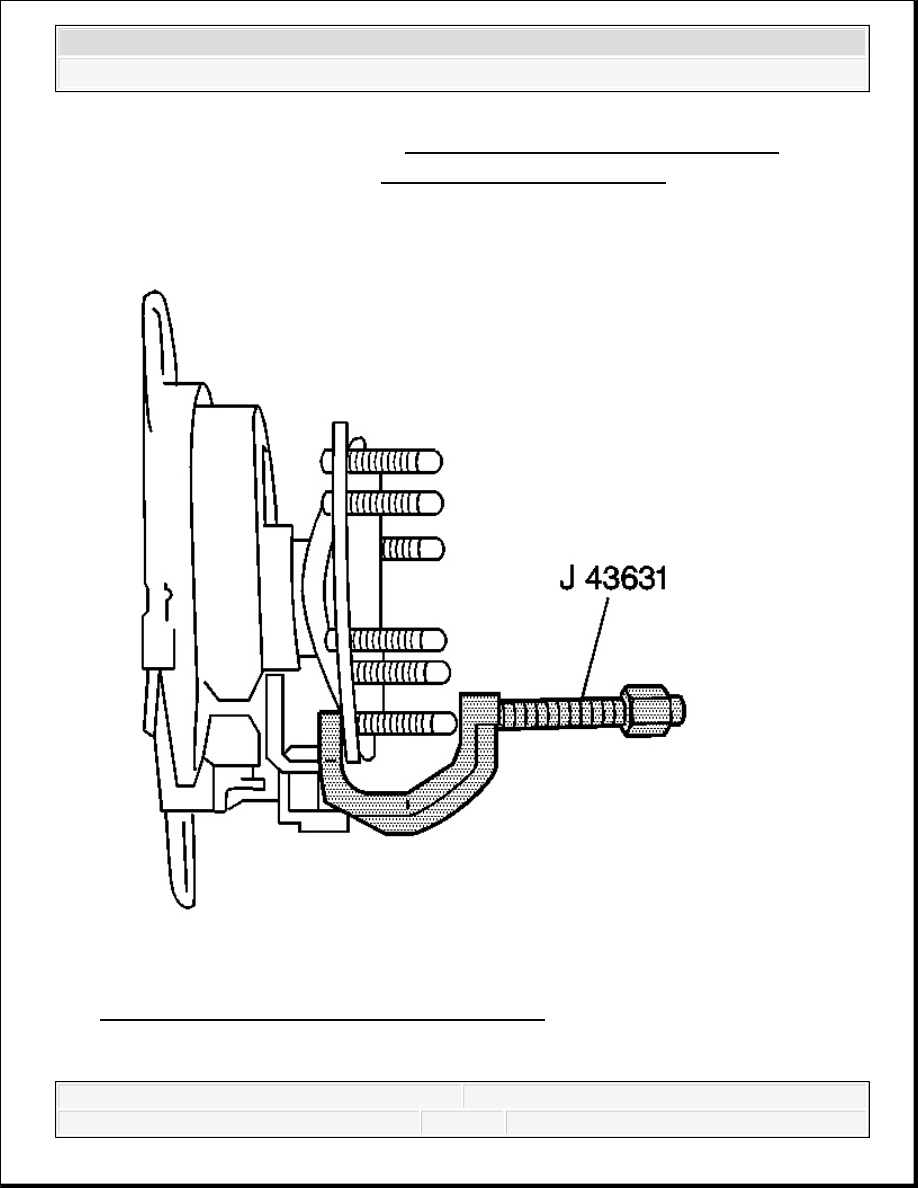
Fig. 30: Removing Wheel Stud From Hub Flange 
Courtesy of GENERAL MOTORS CORP. 


2007 Hummer H3 

2007 SUSPENSION Rear Suspension - H3


4. Remove the wheel stud from the hub flange using the J 43631 .  

5. Remove the wheel stud from the hub flange.  

Installation Procedure 

Fig. 31: View Of Wheel Studs, Hub & Rotor Assembly - Rear (W/Dual Wheels) 
Courtesy of GENERAL MOTORS CORP. 

1. Install the new stud into the hub flange hole using firm hand pressure.  

2. Install 4 washers to the new wheel stud.  


2007 Hummer H3 

2007 SUSPENSION Rear Suspension - H3


3. Thread a wheel nut onto the new stud with the flat side facing the front hub flange.  

4. Tighten the lug nut until the stud contacts the back of the hub flange.  

5. Remove the wheel nut.  

6. Remove the washers.  

7. Install the brake rotor. Refer to Rear Brake Rotor Replacement .  

8. Install the tire and wheel. Refer to Tire and Wheel Removal and Installation .  

9. Remove the safety stands.  

10. Lower the vehicle.  

DESCRIPTION AND OPERATION 

GENERAL DESCRIPTION 

These vehicles use a leaf spring and a solid rear axle suspension system. 

The rear axle assembly is attached to multi-leaf springs with U-bolts. The front ends of the springs 
are attached to the frame at the front hangers with bolts and are isolated utilizing rubber bushings. 
The rear ends of the springs are attached to the frame with bolts at the shackles. The shackles also 
utilize rubber bushings for isolation. Shackles allow the springs to change position while the 
vehicle is in motion. 

Two direct double-acting shock absorbers provide ride control. The shock absorbers are angle-
mounted between the frame. The shock absorbers are attached to the anchor plate. 

The rear spring steel stabilizing shaft helps minimize body roll and sway during cornering. The 
rear stabilizer shaft is connected to the rear axle and the frame with the following components: 


The rubber insulators  


The clamps  


The link assemblies  

SPECIAL TOOLS AND EQUIPMENT 

SPECIAL TOOLS 

Special Tools 

Illustration

Tool Number/Description


2007 Hummer H3 

2007 SUSPENSION Rear Suspension - H3


J 21474-01 

Control Arm Bushing Set

J 43631 

Ball Joint Remover


2007 Hummer H3 

2007 SUSPENSION Rear Suspension - H3


Content   ..  1602  1603  1604  1605   ..