Hummer H3. Manual - part 1401


  Index      Hummer     Hummer H3 - service repair manual 2006-2009 year


Search            


Content   ..  1399  1400  1401  1402   ..


Hummer H3. Manual - part 1401
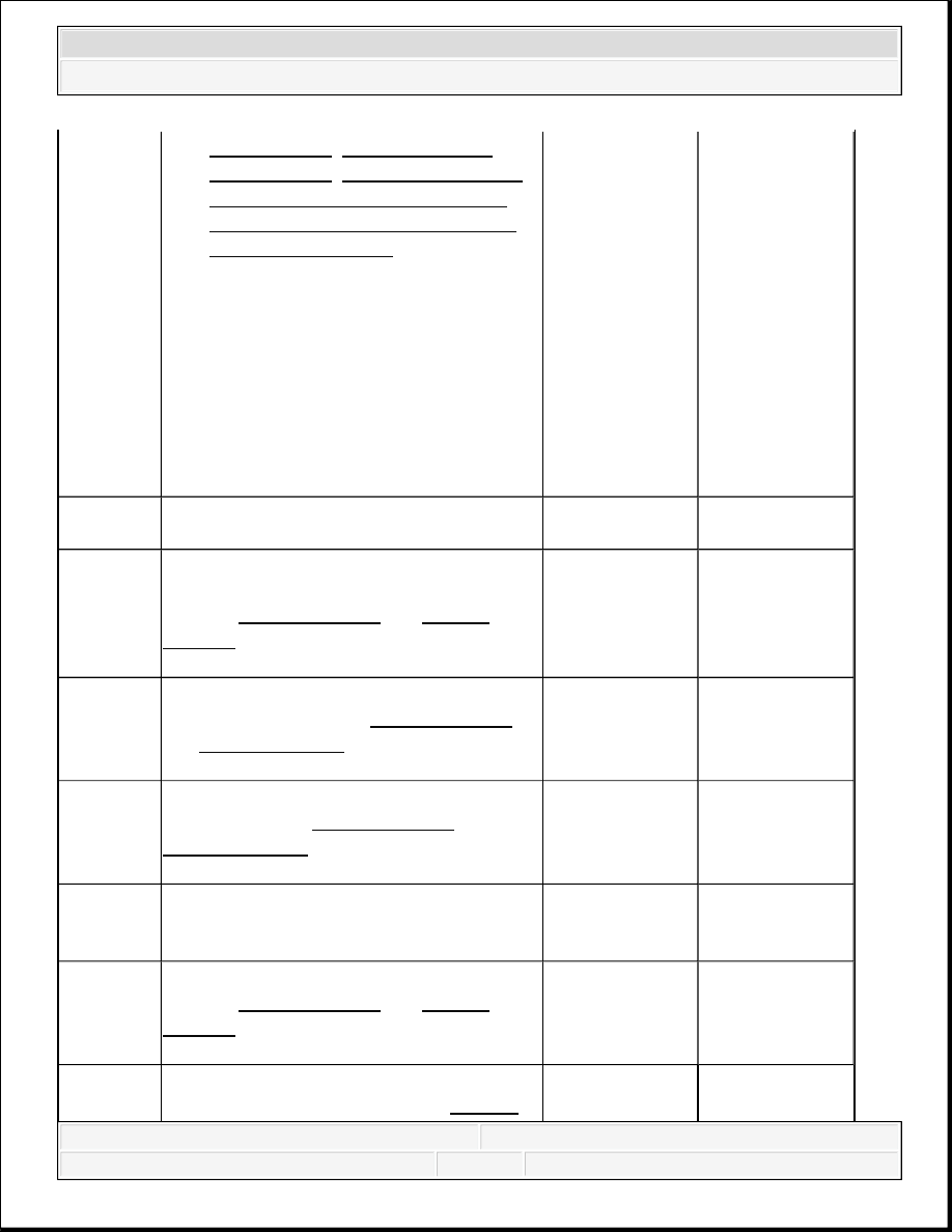


3 

ReplacementTail Lamp Bulb 
Replacement
Instrument Cluster 
Replacement (Left Hand Drive)
 or 
Instrument Cluster Replacement 
(Right Hand Drive)
 .  

3. Turn ON the ignition, with the engine 

OFF.  

4. Connect a test lamp between the 

ground circuit and the supply voltage 
circuit of the inoperative bulb socket.  

5. With a scan tool, command the 

inoperative turn signal ON and OFF.  

Does the test lamp illuminate?

Go to Step 4 

Go to Step 5 

4 

Does the test lamp remain illuminated with 
each command?

Go to Step 7 

Go to Step 8 

5 

Test for a short to ground, open or high 
resistance in the supply voltage circuit. 
Refer to Circuit Testing and Wiring 
Repairs
 . 
Did you find and correct the condition?

Go to Step 15 

Go to Step 6 

6 

Test for an open or high resistance in the 
ground circuit. Refer to Circuit Testing 
and Wiring Repairs . 
Did you find and correct the condition?

Go to Step 15 

Go to Step 11 

7

Test the supply voltage circuit for a short to 
voltage. Refer to Circuit Testing and 
Wiring Repairs . 
Did you find and correct the condition?

Go to Step 15 

Go to Step 11 

8

Does the condition only exist with the turn 
signal indicator in the instrument panel 
cluster (IPC)?

Go to Step 9 

Go to Step 10 

9

Inspect for poor connections at the IPC. 
Refer to Circuit Testing and Wiring 
Repairs
 . 
Did you find and correct the condition?

Go to Step 15 

Go to Step 12 

Inspect for poor connections at the 
inoperative bulb socket. Refer to Circuit 


2007 Hummer H3 

2007 ACCESSORIES & EQUIPMENT Lighting - H3


DTC B0530 (W/O RPO CW9) 

Circuit Description 

When the body control module (BCM) receives a right turn signal ON command from the turn 
signal switch, the BCM will apply voltage to the right turn signal indicator supply voltage circuit. 
The turn signal flasher, which is integrated within the BCM, will flash the right turn signal 
indicator lamp in the instrument panel cluster (IPC) simultaneously with the turn signal lamps. 

DTC Descriptor 

This diagnostic procedure supports the following DTC: 

10

Testing and Wiring Repairs . 
Did you find and correct the condition?

Go to Step 15 

Go to Step 13 

11

Inspect for poor connections at the harness 
connector of the body control module 
(BCM). Refer to Circuit Testing and 
Wiring Repairs . 
Did you find and correct the condition?

Go to Step 15 

Go to Step 14 

12 

Replace the IPC. Refer to Control 
Module References
 for replacement, setup 
and programming. 
Did you complete the replacement?

Go to Step 15 

-

13

Replace the inoperative bulb. Refer to 
Daytime Running Lamp Bulb 
Replacement
 or Tail Lamp Bulb 
Replacement

Did you complete the replacement?

Go to Step 15 

-

14 

Replace the BCM. Refer to Control 
Module References
 for replacement, setup 
and programming. 
Did you complete the replacement?

Go to Step 15 

-

15

1. Use the scan tool in order to clear the 

DTCs.  

2. Operate the vehicle within the 

Conditions for Running the DTC as 
specified in the supporting text.  

Does the DTC reset?

Go to Step 2 

System OK


2007 Hummer H3 

2007 ACCESSORIES & EQUIPMENT Lighting - H3


DTC B0530 Right Turn Signal Circuit 

Conditions for Running the DTC 

The battery voltage must be between 9-16 volts. 

Conditions for Setting the DTC 

When the BCM receives a right turn signal command and the right turn signal indicator supply 
voltage circuit is open, shorted to ground or shorted to voltage 

Action Taken When the DTC Sets 

The right turn signal indicator in the IPC will not operate or will remain always ON. 

Conditions for Clearing the MIL/DTC 


This DTC will clear on current status after the condition for setting the fault is corrected.  


A history DTC will clear after 100 consecutive ignition cycles without a fault present.  


History and current DTCs can be cleared using a scan tool.  

Test Description 

The numbers below refer to the step numbers on the diagnostic table. 

4: This step tests if battery positive voltage is constantly being applied to the supply voltage 
circuit.  

5: This step tests if a condition exists in the supply voltage circuit.  

6: This step tests if a condition exists in the ground circuit.  

10: After replacement of the IPC, you must calibrate the new cluster for proper operation.  

11: After replacement of the BCM, you must calibrate the new module for proper 
operation.  

DTC B0530 (W/O RPO CW9) 

Step

Action

Yes

No

Schematic Reference: Fog Lights Schematics 
Connector End View Reference: Lighting Systems Connector End ViewsDisplays 
and Gages Connector End Views
 or Data Communication Connector End Views 

1

Did you perform the Diagnostic System 
Check - Vehicle?

Go to 
Diagnostic 


2007 Hummer H3 

2007 ACCESSORIES & EQUIPMENT Lighting - H3


Go to Step 2 

System Check - 
Vehicle
 

2

1. Turn ON the ignition, with the engine 

OFF.  

2. Activate the turn signals.  

Do the exterior turn signals operate 
correctly?

Go to Step 3 

Go to 
Symptoms - 
Lighting 
Systems

3

1. Turn OFF the ignition.  

2. Remove the instrument panel cluster 

(IPC). Refer to Instrument Cluster 
Replacement (Left Hand Drive)
 or 
Instrument Cluster Replacement 
(Right Hand Drive)
 .  

3. Turn ON the ignition, with the engine 

OFF.  

4. Connect a test lamp between the 

ground circuit and the right turn 
signal indicator supply voltage circuit 
at the IPC connector.  

5. Activate the inoperative turn signal 

ON and OFF.  

Does the test lamp illuminate?

Go to Step 4 

Go to Step 5 

4 

Does the test lamp remain illuminated with 
each command?

Go to Step 7 

Go to Step 8 

5 

Test for a short to ground, open or high 
resistance in the right turn signal indicator 
supply voltage circuit. Refer to Circuit 
Testing
 and Wiring Repairs . 
Did you find and correct the condition?

Go to Step 12 

Go to Step 6 

6 

Test for an open or high resistance in the 
ground circuit. Refer to Circuit Testing 
and Wiring Repairs . 
Did you find and correct the condition?

Go to Step 12 

Go to Step 9 

7

Test the right turn signal indicator supply 
voltage circuit for a short to voltage. Refer 


2007 Hummer H3 

2007 ACCESSORIES & EQUIPMENT Lighting - H3


Content   ..  1399  1400  1401  1402   ..