Hummer H3. Manual - part 1250


  Index      Hummer     Hummer H3 - service repair manual 2006-2009 year


Search            


Content   ..  1248  1249  1250  1251   ..


Hummer H3. Manual - part 1250


REPAIR INSTRUCTIONS 

HORN REPLACEMENT 

Removal Procedure 

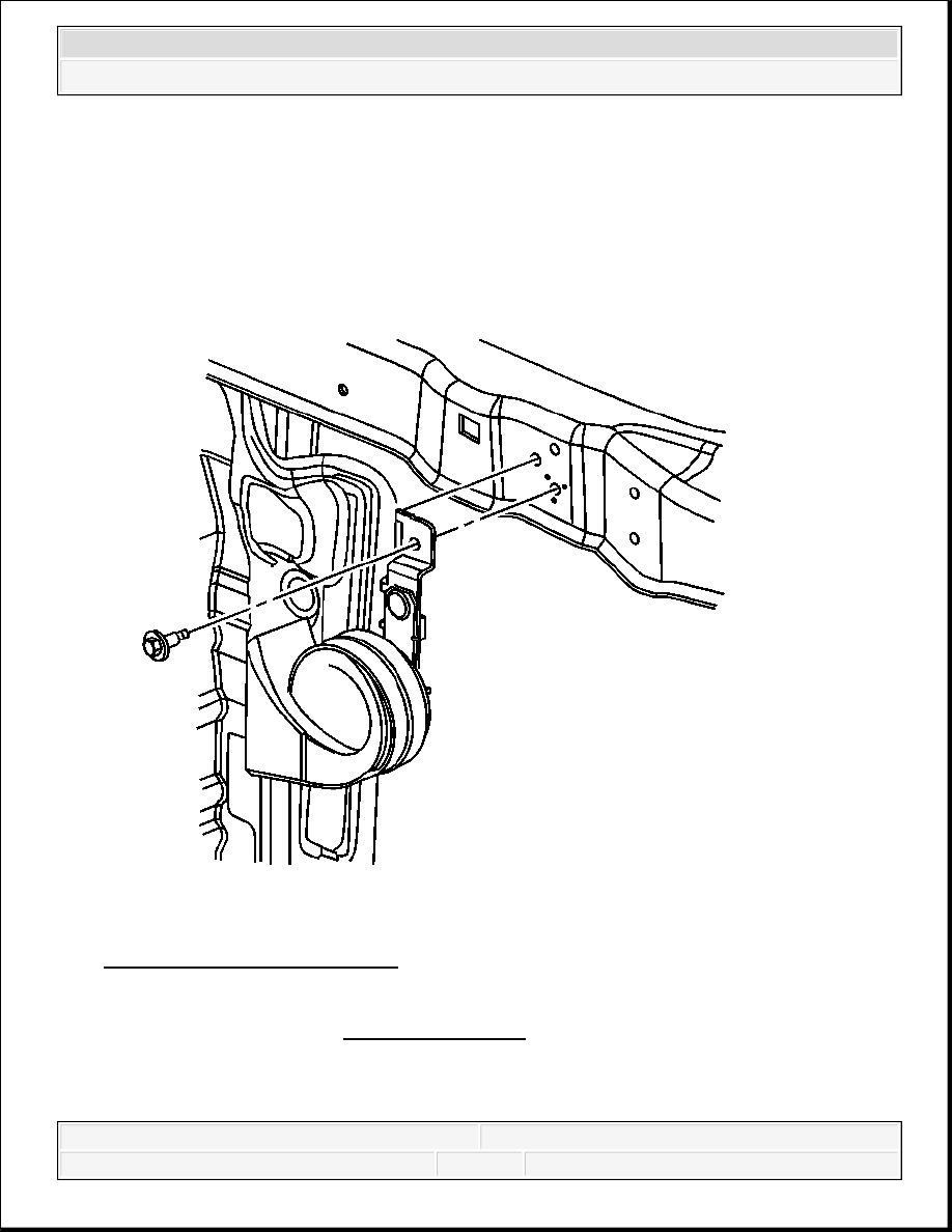
Fig. 6: View Of Horn Assembly 
Courtesy of GENERAL MOTORS CORP. 

1. Remove the grille. Refer to Grille Replacement .  

2. Disconnect the horn assembly electrical connector.  

3. Remove the bolt that retains the horn assembly to the radiator support.  


2007 Hummer H3 

2007 ACCESSORIES & EQUIPMENT Horns - H3


4. Remove the horn assembly from the body.  

Installation Procedure 

Fig. 7: View Of Horn Assembly 
Courtesy of GENERAL MOTORS CORP. 

1. Install the horn assembly to the radiator support. 

2. Install the bolt that retains the horn assembly to the radiator support. 

NOTE:

Refer to FASTENER NOTICE .


2007 Hummer H3 

2007 ACCESSORIES & EQUIPMENT Horns - H3


Tighten: Tighten the bolt to 10 N.m (88 lb in). 

3. Connect the horn assembly electrical connector.  

4. Install the grille. Refer to Grille Replacement .  

HORN SWITCH REPLACEMENT 

The horn switch is an internal component of the steering wheel inflator module and is not 
serviceable. If the horn switch fails and needs replacement. Refer to Inflatable Restraint 
Steering Wheel Module Replacement
 . 

DESCRIPTION AND OPERATION 

HORNS SYSTEM DESCRIPTION AND OPERATION 

System Description 

The horn system consists of the following components: 


The HORN fuse  


The horn relay  


The horn switch  


The horn assembly  


The body control module (BCM)  

System Operation 

The vehicle horn system is activated under the following conditions: 


The horn switch is depressed.  


The BCM commands the horns on. The BCM commands the horns on under any of the 
following conditions: 


When the content theft deterrent system detects a vehicle intrusion. For further 
information refer to Content Theft Deterrent (CTD) Description and Operation .  


When the panic button is depressed on the remote control door lock transmitter. For 
further information refer to Keyless Entry System Description and Operation .  


When the OnStar® system is used to sound the horns (if equipped.) For further 
information refer to OnStar Description and Operation .  


When the unlock button on the keyless entry transmitter is pressed, a horn chirp will 


2007 Hummer H3 

2007 ACCESSORIES & EQUIPMENT Horns - H3


sound to notify the driver that the vehicle has been unlocked. For further information 
refer to Keyless Entry System Description and Operation .  


When the lock button on the keyless entry transmitter is pressed twice within 5 
seconds, a horn chirp will sound to notify the driver that the vehicle has been locked. 
For further information refer to Keyless Entry System Description and Operation . 

Circuit Operation 

Battery positive voltage is applied at all times to the horn relay coil and the horn relay switch. 
Pressing the horn switch applies ground to the horn relay control circuit. The BCM may also 
apply ground to the horn relay control circuit as described above. When the horn relay control 
circuit is grounded, the horn relay is energized and battery positive voltage is applied to the horns 
through the horn fuse supply voltage circuit. The horns sound as long as ground is applied to the 
horn relay control circuit. 


2007 Hummer H3 

2007 ACCESSORIES & EQUIPMENT Horns - H3


Content   ..  1248  1249  1250  1251   ..