Hummer H3. Manual - part 1015


  Index      Hummer     Hummer H3 - service repair manual 2006-2009 year


Search            


Content   ..  1013  1014  1015  1016   ..


Hummer H3. Manual - part 1015
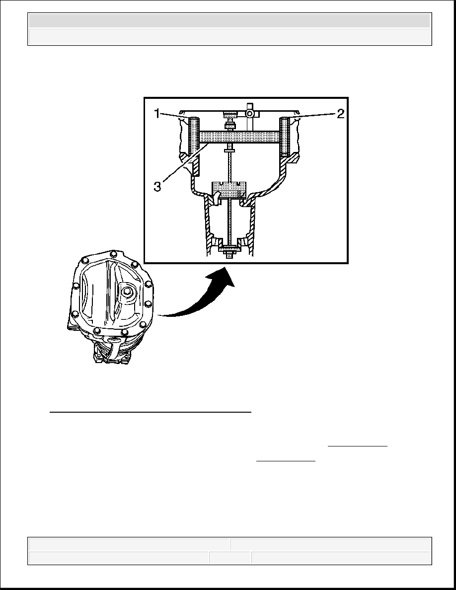


Fig. 118: Assembling J 21777-45 & J 21777-1 
Courtesy of GENERAL MOTORS CORP. 

7. Assemble the J 21777-45 (1, 2) to the J 23597-1 (3) as shown. See Special Tools.  

8. Rotate the J 23597-1 within the J 21777-45 . See Special Tools. The J 23597-1 must rotate 

back and forth freely within the discs. If the J 23597-1 does not rotate freely, disassemble 
the components, inspect for proper seating and/or mis-aligned components and re-assemble. 


2007 Hummer H3 

2007 Driveline/Axle Rear Drive Axle - H3


Fig. 119: Identifying J 21777-1 & J 44416-3 
Courtesy of GENERAL MOTORS CORP. 

9. Align the plunger of the J 23597-1 (1) to the J 23597-11 (2).  

10. Install the J 8001 to the J 23597-1 as follows: 


2007 Hummer H3 

2007 Driveline/Axle Rear Drive Axle - H3


1. Loosely clamp the J 8001 onto the stem on the J 23597-1.  

2. Place the contact pad of the J 8001 onto the mounting post of the J 23597-1.  

3. With the contact pad of the J 8001 touching the mounting post of the J 23597-1, 

loosen the lock nut on the J 8001 and push down on the J 8001 until the needle the 
8001
 has turned 3/4 of a turn clockwise.  

4. Tighten the clamp on the J 8001 finger tight.  

11. Move the plunger of the J 23597-1 back and forth until the needle of the J 8001 indicates 

the greatest deflection. 

The deflection is the point where the needle changes direction. 

Fig. 120: Measuring Necessary Shim Thickness 
Courtesy of GENERAL MOTORS CORP. 

12. At the greatest point of deflection, move the housing of the J 8001 until the needle indicates 


2007 Hummer H3 

2007 Driveline/Axle Rear Drive Axle - H3


ZERO.  

13. Move the plunger of the J 23597-1 back and forth again to verify the zero setting. Adjust the 

housing of the J 8001 as necessary to set the needle to zero.  

14. Rotate the plunger of the J 23597-1 away from the J 23597-11 until it no longer touches the 

J 23597-11 or the J 21777-29.  

15. The value indicated on the J 8001 is the thickness of the shim needed in order to set the 

depth of the pinion.  

16. Select the shim that indicates the proper thickness. Measure the shim with a micrometer in 

order to verify that the thickness is correct.  

17. Remove the pinion depth setting tools.  

18. Remove the pinion bearings.  

19. Install the pinion shim between the pinion gear and the inner pinion bearing. Refer to Drive 

Pinion Bearings Replacement.  

DIFFERENTIAL SIDE BEARING PRELOAD ADJUSTMENT 

Tools Required 


J 22779 Side Bearing Backlash Gage  


J 25588 Side Bearing Shim Installer  

Wedge Method 

1. Install the drive pinion, if necessary. Refer to Drive Pinion and Ring Gear Replacement.  

2. Measure the rotating torque of the drive pinion using an inch-pound torque wrench. Record 

the measurement. 

IMPORTANT:


The differential side bearing preload adjustment must be 
completed before the backlash adjustment can be started.  


In order to maintain the original backlash, adjust the 
differential case side bearing preload by changing the 
thickness of the left and the right side shim packs equally.  


Measure the service shims and the spacers one at a time. 
Add the measurements together in order to obtain the total 
thickness of the left or the right side shim pack.  


Do not use or reuse the original cast iron production shims. 
Use service shims and spacers instead.  


2007 Hummer H3 

2007 Driveline/Axle Rear Drive Axle - H3


Content   ..  1013  1014  1015  1016   ..