Hummer H2. Manual - part 940


  Index      Hummer     Hummer H2 - service repair manual 2004 year


Search            


Content   ..  938  939  940  941   ..


Hummer H2. Manual - part 940


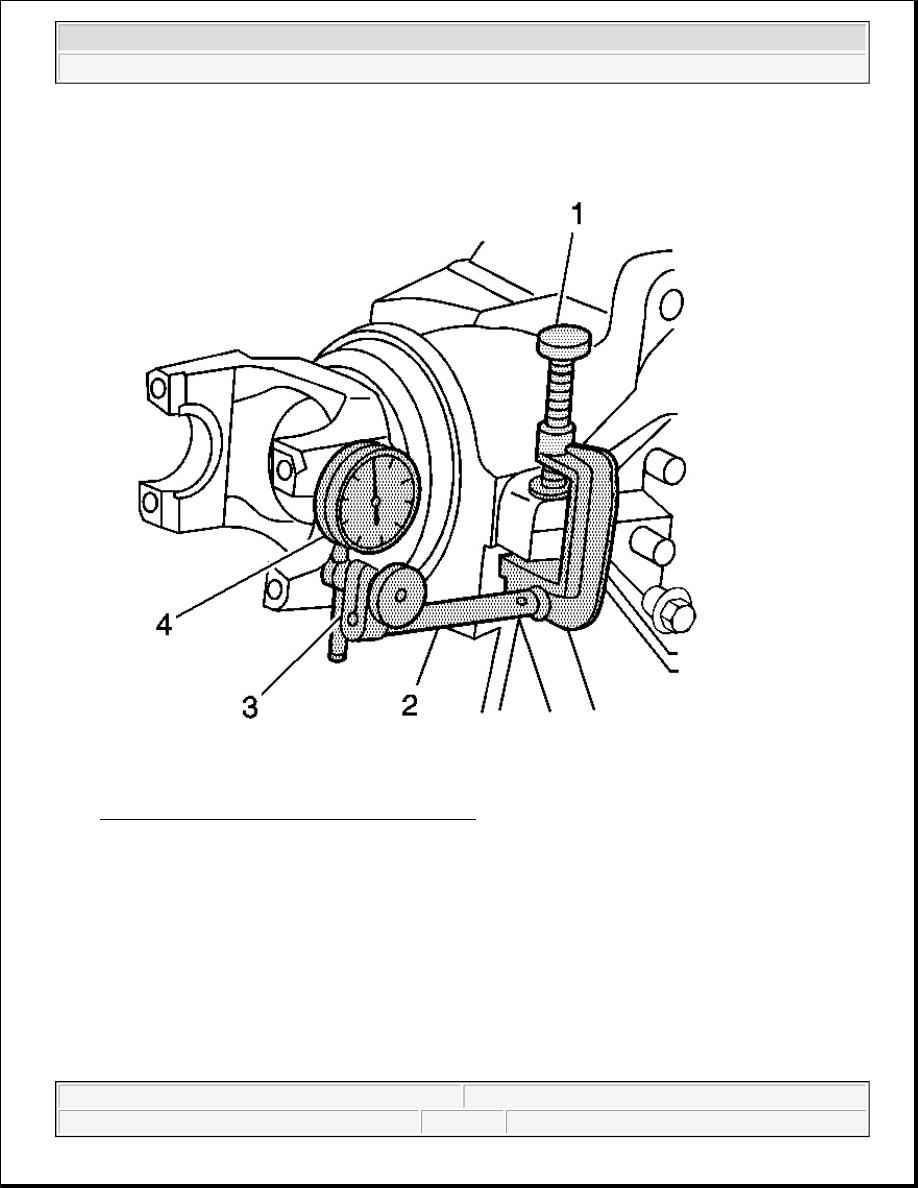
Fig. 126: Installing J 8001-1, J 8001-2 & J 8001-3 
Courtesy of GENERAL MOTORS CORP. 

2. Install the J 8001-1 (1, 2), the J 8001-2 (3), and the J 8001-3 (4) as shown. 

Ensure that the button contacts the outer edge of the pinion yoke and that the plunger is at a right angle to 
the pinion yoke. 

3. Move the pinion yoke back and forth through the pinion yoke's free play while not allowing the ring gear 

to move.  

4. Record the dial indicator reading.  

5. To determine the actual backlash, divide the dial indicator reading by 2. 


2004 Hummer H2 

2004 DRIVELINE/AXLE Front Drive Axle - Hummer H2


An actual dial indicator reading of 0.16 mm (0.006 in) means that there is actually 0.08 mm (0.003 in) 
backlash. 

Specification: The backlash between the ring gear and the drive pinion should be between 0.08-0.25 mm 
(0.003-0.010 in) with a preferred specification of 0.13-0.18 mm (0.005-0.007 in). 

6. If the backlash is too small, increase the backlash by turning the left differential adjuster nut sleeve in one 

notch using the J 36615 and the right differential adjuster nut sleeve out one notch using theJ 36599-A . 
See Special Tools and Equipment .  

7. If the backlash is too large, decrease the backlash by turning the right differential adjuster nut sleeve in 

one notch using the J 36599-A and the left differential adjuster nut sleeve out one notch using the 
36615
 . See Special Tools and Equipment .  

8. Recheck the backlash and adjust as necessary.  

9. Recheck the rotating torque of the pinion and differential assembly and adjust as necessary.  

10. Once the backlash and rotating torque of the pinion and differential assembly is correct, perform a gear 

tooth contact pattern check to ensure proper contact between the pinion and the ring gear. Refer to Gear 
Tooth Contact Pattern Inspection
 .  

11. Complete the assembly of the differential carrier. Refer to Differential Carrier Assembly - Final 

Assembly .  

DIFFERENTIAL CARRIER ASSEMBLY - FINAL ASSEMBLY 

Tools Required 

z

J 36609 Axle Tube Bearing Installer. See Special Tools and Equipment .  

z

J 45225 Axle Seal Installer. See Special Tools and Equipment .  

z

J 45755 Front Axle Bushing Remover/Installer - 9. See Special Tools and Equipment .25 inch Axle  

z

J 8092 Universal Driver Handle - 3/4 in - 10. See Special Tools and Equipment .  

IMPORTANT: When adjusting the backlash, observe the following: 

z

Always turn the left and the right differential adjuster nut sleeves in 
equal amounts.  

z

Turning the differential adjuster nut sleeves one notch will change 
the backlash about 0.08 mm (0.003 in).  


2004 Hummer H2 

2004 DRIVELINE/AXLE Front Drive Axle - Hummer H2


Fig. 127: Bending Right Side Differential Adjuster Nut Lock Tab Over Differential Adjuster Nut 
Sleeve
 
Courtesy of GENERAL MOTORS CORP. 

1. Bend the right side differential adjuster nut lock tab over the differential adjuster nut sleeve. 


2004 Hummer H2 

2004 DRIVELINE/AXLE Front Drive Axle - Hummer H2


Fig. 128: Differential Adjuster Nut Lock 
Courtesy of GENERAL MOTORS CORP. 

2. Install the differential adjuster nut lock. 


2004 Hummer H2 

2004 DRIVELINE/AXLE Front Drive Axle - Hummer H2


Content   ..  938  939  940  941   ..