Hummer H2. Manual - part 761


  Index      Hummer     Hummer H2 - service repair manual 2004 year


Search            


Content   ..  759  760  761  762   ..


Hummer H2. Manual - part 761


as spark plug wires. 
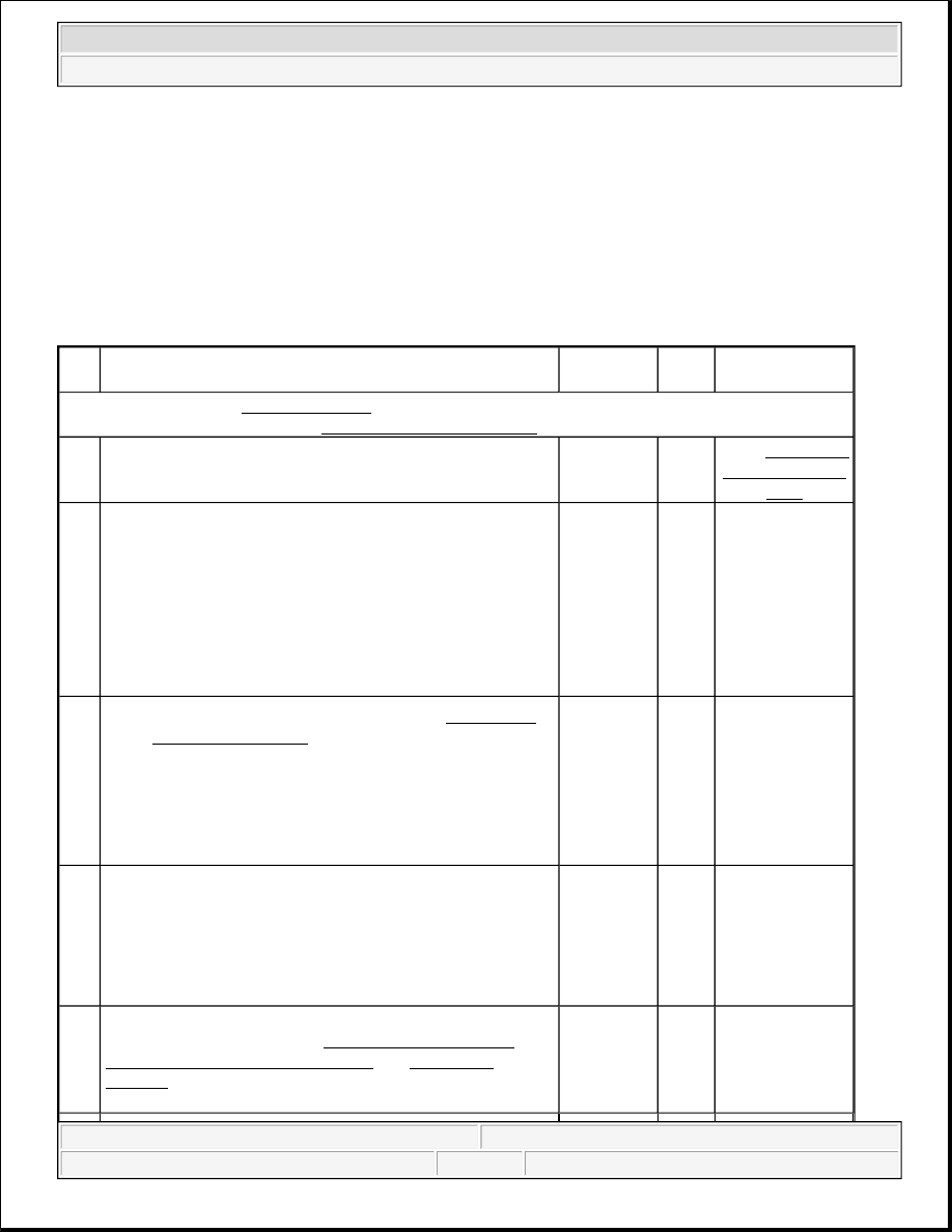
Test Description 

The numbers below refer to the step numbers on the diagnostic table. 

3: This step tests the wheel speed sensor for the proper resistance value.  

4: This step ensures that the wheel speed sensor generates the proper voltage.  

DTC C0035-C0051 

Step 

or

Action

Value(s)

Yes

No

Schematic Reference: ABS Schematics 
Connector End View Reference:ABS Connector End Views

1

Did you perform the ABS Diagnostic System Check?

-

Go to 

Step 2

Go to Diagnostic 

System Check - 

ABS

2

1. Install a scan tool.  

2. Turn ON the ignition.  

3. Set up the scan tool snap shot feature to trigger for 

this DTC.  

4. Drive the vehicle at a speed greater than the specified 

value.  

Does the scan tool indicate that this wheel speed DTC set?

40 km/h (25 

mph)

Go to 

Step 3

Go to Diagnostic 

Aids

3

1. Raise and support the vehicle. Refer to Lifting and 

Jacking the Vehicle in General Information.  

2. Disconnect the wheel speed sensor connector.  

3. Measure the resistance across the wheel speed sensor. 

Does the resistance measure within the specified range?

Front 

Wheels 

800-1600 

ohm 

Rear 

Wheels 

4500-5400 

ohm

Go to 

Step 4

Go to Step 8

4

1. Spin the wheel.  

2. Measure the AC voltage across the wheel speed 

sensor.  

Does the AC voltage measure greater than the specified 
value?

100 mV

Go to 

Step 5

Go to Step 8

5

Inspect for poor connections at the harness connector of the 
wheel speed sensor. Refer to Testing for Intermittent 
Conditions and Poor Connections
 and Connector 
Repairs
 in Wiring Systems. 
Did you find and correct the condition?

-

Go to 

Step 

10

Go to Step 6


2004 Hummer H2 

2004 BRAKES Anti-Lock Brake System - Hummer H2


DTC C0110 

Circuit Description 

The pump motor is an integral part of the BPMV, while the pump motor relay is integral to the EBCM. The 
pump motor relay is not engaged during normal system operation. When ABS or TCS operation is required the 
EBCM activates the pump motor relay and battery power is provided to the pump motor. 

Conditions for Running the DTC 

z

The ignition switch is in the ON position.  

z

Initialization is complete.  

6

1. Disconnect the electronic brake control module 

(EBCM) harness connector.  

2. Install the J 39700 using. See Special Tools and 

Equipment . J 39700-530 to the EBCM harness 
connector only.  

3. Test the wheel speed sensor circuits for the following: 

z

An open  

z

A short to ground  

z

A short to voltage  

z

Shorted together  

Refer to Testing for Intermittent Conditions and Poor 
Connections
 and Wiring Repairs in Wiring Systems.Did 
you find and correct the condition?

-

Go to 

Step 

10

Go to Step 7

7

Inspect for poor connections at the harness connector for the 
EBCM. Refer Testing for Intermittent Conditions and 
Poor Connections
 and Connector Repairs in Wiring 
Systems. 
Did you find and correct the condition?

-

Go to 

Step 

10

Go to Step 9

8

Replace the wheel speed sensor. Refer to Wheel Speed 
Sensor Replacement - Front
 or Wheel Speed Sensor 
Replacement - Rear
 in Rear Suspension. 
Did you complete the replacement?

-

Go to 

Step 

10

-

9

Replace the EBCM. Refer to Electronic Brake Control 
Module Replacement
 . 
Did you complete the repair?

-

Go to 

Step 

10

-

10

1. Use the scan tool in order to clear the DTCs.  

2. Operate the vehicle within the Conditions for 

Running the DTC as specified in the supporting text.  

Does the DTC reset?

-

Go to 

Step 2

System OK


2004 Hummer H2 

2004 BRAKES Anti-Lock Brake System - Hummer H2


Conditions for Setting the DTC 

z

Pump motor voltage is not present 60 milliseconds after activation of the pump motor relay.  

z

Pump motor voltage is present for more than 2.5 seconds with no activation of the pump motor relay.  

z

Pump motor voltage is not present for 40 milliseconds after the pump motor relay is commanded off.  

Action Taken When the DTC Sets 

If equipped, the following actions occur: 

z

The EBCM disables the ABS/TCS for the duration of the ignition cycle.  

z

A malfunction DTC will set.  

z

The ABS indicator turns ON.  

z

The Red BRAKE Warning indicator could turn on.  

Conditions for Clearing the DTC 

z

The condition for the DTC is no longer present and the DTC is cleared with a scan tool.  

z

The electronic brake control module (EBCM) automatically clears the history DTC when a current DTC 
is not detected in 100 consecutive drive cycles.  

Diagnostic Aids 

z

It is very important that a thorough inspection of the wiring and connectors be performed. Failure to 
carefully and fully inspect wiring and connectors may result in misdiagnosis, causing part replacement 
with reappearance of the malfunction.  

z

Thoroughly inspect any circuitry that may be causing the complaint for the following conditions: 

{

Backed out terminals  

{

Improper mating  

{

Broken locks  

{

Improperly formed or damaged terminals  

{

Poor terminal-to-wiring connections  

{

Physical damage to the wiring harness  

z

The following conditions may cause an intermittent malfunction: 

{

A poor connection  

{

Rubbed-through wire insulation  

{

A broken wire inside the insulation  

z

If an intermittent malfunction exists refer to Testing for Intermittent Conditions and Poor 
Connections
 in Wiring Systems.  

Test Description 

The number below refers to the step number on the diagnostic table.


2004 Hummer H2 

2004 BRAKES Anti-Lock Brake System - Hummer H2


3: Tests the pump motor circuits of the BPMV for a short to the housing of the BPMV. The wiring from 
the BPMV to the EBCM should not be repaired.  

DTC C0110 

Step

Action

Value

(s)

Yes

No

Schematic Reference: ABS Schematics 
Connector End View Reference:ABS Connector End Views

1

Did you perform the ABS Diagnostic System Check?

-

Go to 

Step 2

Go to Diagnostic 

System Check - 

ABS

2

1. Disconnect the EBCM harness connector.  

2. Connect the J 39700 Universal Pinout Box using the. See 

Special Tools and Equipment . J 39700-530 Cable 
Adapter to the EBCM harness connector only.  

3. Test both ground circuits of the EBCM including the 

EBCM ground for a high resistance or an open. Refer to 
Circuit Testing and Wiring Repairs in Wiring Systems.  

4. Test the Battery Positive Voltage circuits for an open, high 

resistance, or a short to ground. Refer to Circuit Testing 
and Wiring Repairs in Wiring Systems.  

orDid you find and correct the condition?

-

Go to 

Step 8

Go to Step 3

3

1. Disconnect the pump motor harness pigtail connector of 

the BPMV.  

2. Measure the resistance between each pump motor control 

circuit and the housing of the BPMV at the pump motor 
harness pigtail connector of the BPMV.  

Does the resistance measure less than the specified value?

5 ohm

Go to 

Step 4

Go to Step 5

4

Inspect for poor connections at the pump motor harness pigtail 
connector of the BPMV. Refer to Testing for Intermittent 
Conditions and Poor Connections
 and Connector Repairs in 
Wiring Systems. 
Did you find and correct the condition?

-

Go to 

Step 8

Go to Step 6

5

Inspect for poor connections at the harness connector of the 
EBCM. Refer to Testing for Intermittent Conditions and Poor 
Connections
 and Connector Repairs in Wiring Systems. 
Did you find and correct the condition?

-

Go to 

Step 8

Go to Step 7

6

Replace the BPMV. Refer to Brake Pressure Modulator Valve 
(BPMV) Replacement
 . 
Did you complete the repair?

-

Go to 

Step 8

-

7

Replace the EBCM. Refer to Electronic Brake Control Module 
Replacement
 . 

-

Go to 


2004 Hummer H2 

2004 BRAKES Anti-Lock Brake System - Hummer H2


Content   ..  759  760  761  762   ..